
Lens Driving Device, Camera Module and Optical Apparatus

a technology of lens driving device and optical apparatus, which is applied in the direction of dynamo-electric machines, instruments, printing, etc., can solve the problems of lowering the auto-focusing speed, and the control of the lens driving device may encounter a problem

Active Publication Date: 2016-07-21
LG INNOTEK CO LTD
View PDF3 Cites 37 Cited by
  • Summary
  • Abstract
  • Description
  • Claims
  • Application Information

AI Technical Summary

Benefits of technology

The present patent is for a lens driving device with auto-focus and handshake compensation functions. The device receives accurate position information from a bobbin and holder member to achieve precise lens movement. Damping members may be coated between parts of the elastic member and the holder member to stabilize the change in frequency. The technical effects of this invention are improved autofocus and handshaking compensation in a camera module with a lens driving device.

Problems solved by technology

In addition, the control of the lens driving device may encounter a problem, as an internal space of the camera module is becoming narrower according to requirement for miniaturizing the camera module and a shape of an elastic member is formed in response to such requirement.
In addition, the control of the lens driving device may encounter a problem caused by vibration frequency of the elastic member, when the camera module performs auto-focus and handshake compensation operations.
The excessive scrambling of the driver may reduce setting time to cause a problem of lowered auto-focusing speed.

Method used


Image

  • Lens Driving Device, Camera Module and Optical Apparatus
  • Lens Driving Device, Camera Module and Optical Apparatus
  • Lens Driving Device, Camera Module and Optical Apparatus

Examples


Embodiment Construction

[0086]Hereinafter, exemplary embodiments of the present disclosure will be described with reference to the exemplary drawings. In designating elements in the drawings as reference numerals, wherever possible, the same reference numerals are used to refer to the same element, even though the same elements are illustrated in different drawings. In addition, in describing exemplary embodiments of the present disclosure, when it is determined that a detailed description about known function or structure relating to the present disclosure may disturb understanding of exemplary embodiments of the present disclosure, the detailed description may be omitted.

[0087]In addition, in describing elements of exemplary embodiments of the present disclosure, the terms such as “first”, “second”“A”, “B”, “(a)” and “(b)” may be used. However, such terms are used merely to distinguish a particular element from another element, and therefore, essence, order or sequence of the relevant elements shall not ...


PUM


Abstract

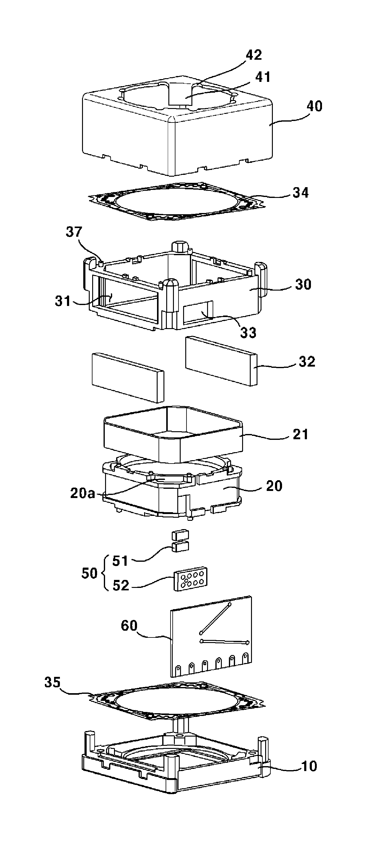
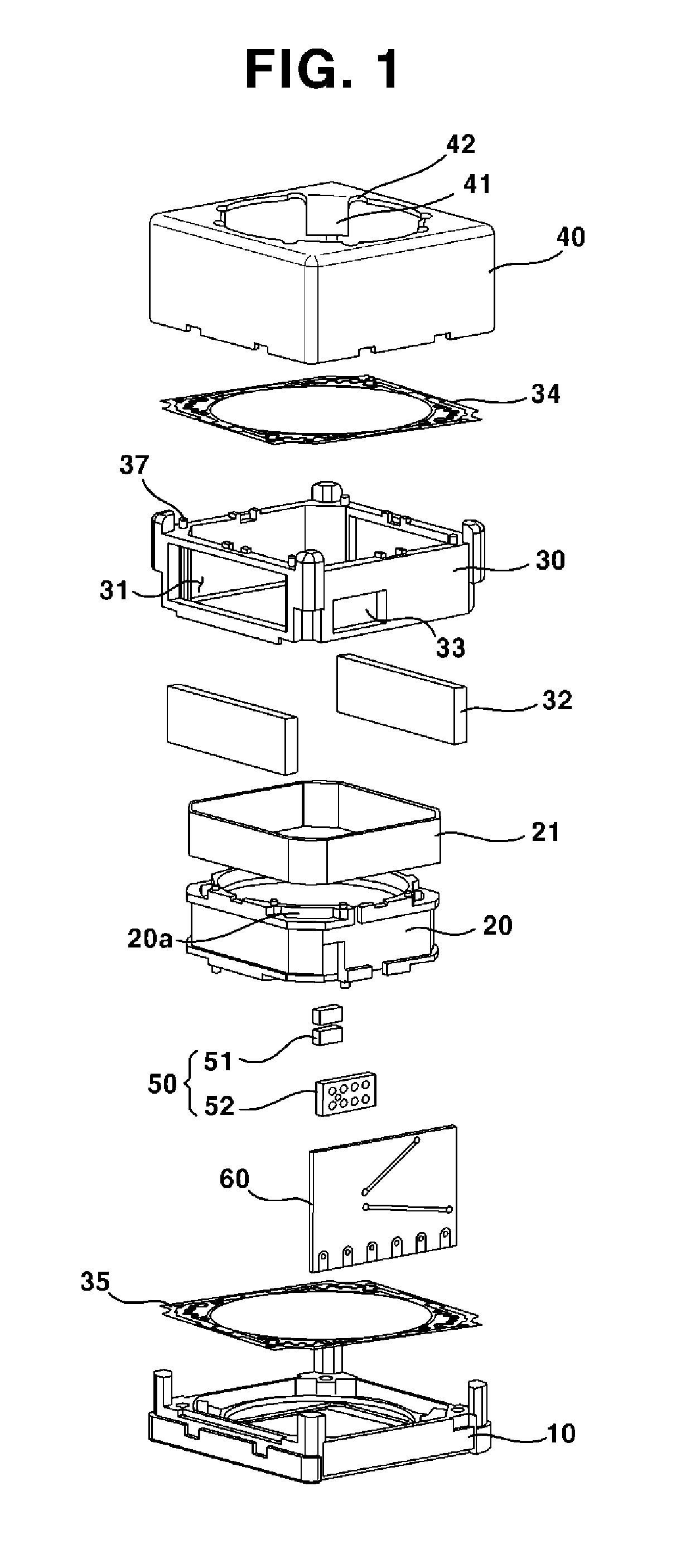
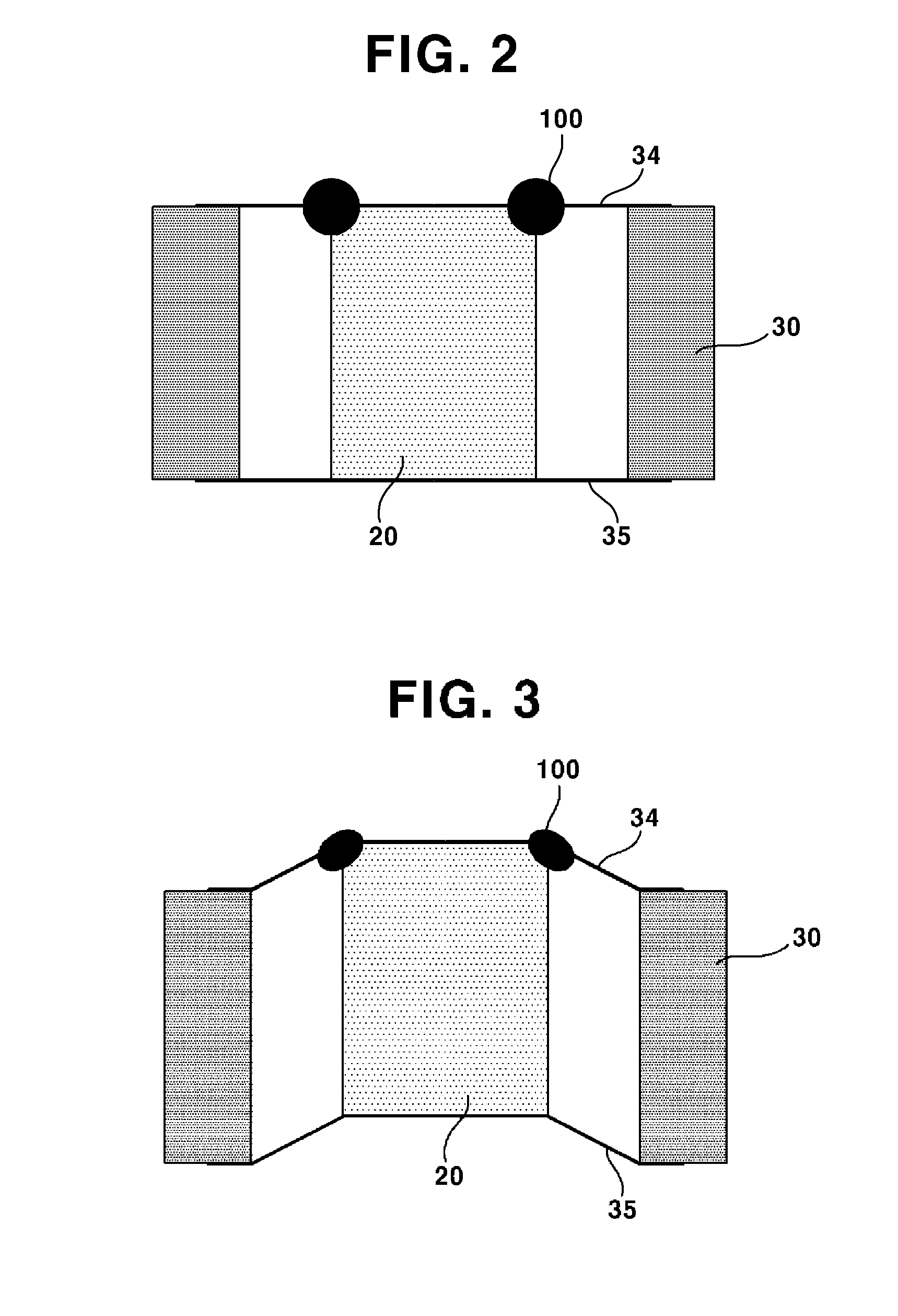
A lens driving device is provided, including: a cover member; a bobbin installed with at least one lens and having a coil unit arranged on an outer circumferential surface of the bobbin; a magnet arranged at a positon corresponding to that of the coil unit; first and second elastic members, where one end of each of the first and second elastic members may be respectively coupled to an upper surface and a lower surface of the bobbin and supporting movement of the bobbin in an optical axis direction; a detection unit configured to detect movement of the bobbin in a direction parallel to the optical axis direction; a damping member arranged at a connecting portion between the bobbin and the first elastic member; and a support unit provided at at least one of the bobbin and the first elastic member and maintaining an arranged position of the damping member.

Description

CROSS-REFERENCE TO RELATED APPLICATIONS[0001]This application claims the benefit under 35 U.S.C. §119 of Korean Application Nos. 10-2015-0009257 filed Jan. 20, 2015, 10-2015-0011856 filed Jan. 26, 2015, and of 10-2015-0014256 filed Jan. 29, 2015, which are hereby incorporated by reference in their entirety.TECHNICAL FIELD[0002]The present exemplary embodiments relate to a lens driving device, a camera module and an optical apparatus.BACKGROUND[0003]A camera module may include an image sensor, a PCB (Printed Circuit Board) configured to deliver electric signals to the image sensor installed on the PCB, an infrared cut-off filter configured to block light in infrared area from being incident on the image sensor, and an optical system including at least one lens configured to deliver an image to the image sensor. Here, a lens driving device configured to perform auto-focus function and handshake compensation function may be installed in the optical system.[0004]The lens driving device ...

Claims


Application Information

Patent Timeline
Patent Type & Authority Applications(United States)
IPC IPC(8): G02B7/08G02B27/64G02B7/09G02B7/28G03B5/00G03B13/36
CPCG02B27/646G02B7/08G02B7/09G02B7/28G03B5/00G03B13/36H02K33/18
Inventor PARK, SANG OKLEE, SEONG MINLEE, JUN TAEKSON, BYUNG WOOKMIN, SANG JUNYOO, KYOUNG HO
Owner LG INNOTEK CO LTD
Learn More