Wind power conversion system

Active Publication Date: 2016-07-21
DELTA ELECTRONICS INC
View PDF13 Cites 16 Cited by
  • Summary
  • Abstract
  • Description
  • Claims
  • Application Information

AI Technical Summary

Benefits of technology

[0006]An object of the present invention provides a wind power conversion system. The wind power conversion system comprises plural first converting circuits and a second converting circuit. The plural second generator-side terminals of the second converting circuit are electrically connected with the corresponding first generator-side terminals of the plural first converting circuits in series. The second network-side terminal of the second converting circuit is electrically connected with the corresponding secondary winding of the plural secondary windings of an isolati

Problems solved by technology

Nowadays, the energy crisis problem becomes more serious.
Under this circumstance, the overall cost associated with the factory or instrument is high.
Consequently, the method of controlling the power components is more complicated.
Moreover, since more power components are employed, the

Method used


Image

  • Wind power conversion system
  • Wind power conversion system
  • Wind power conversion system

Examples


first embodiment

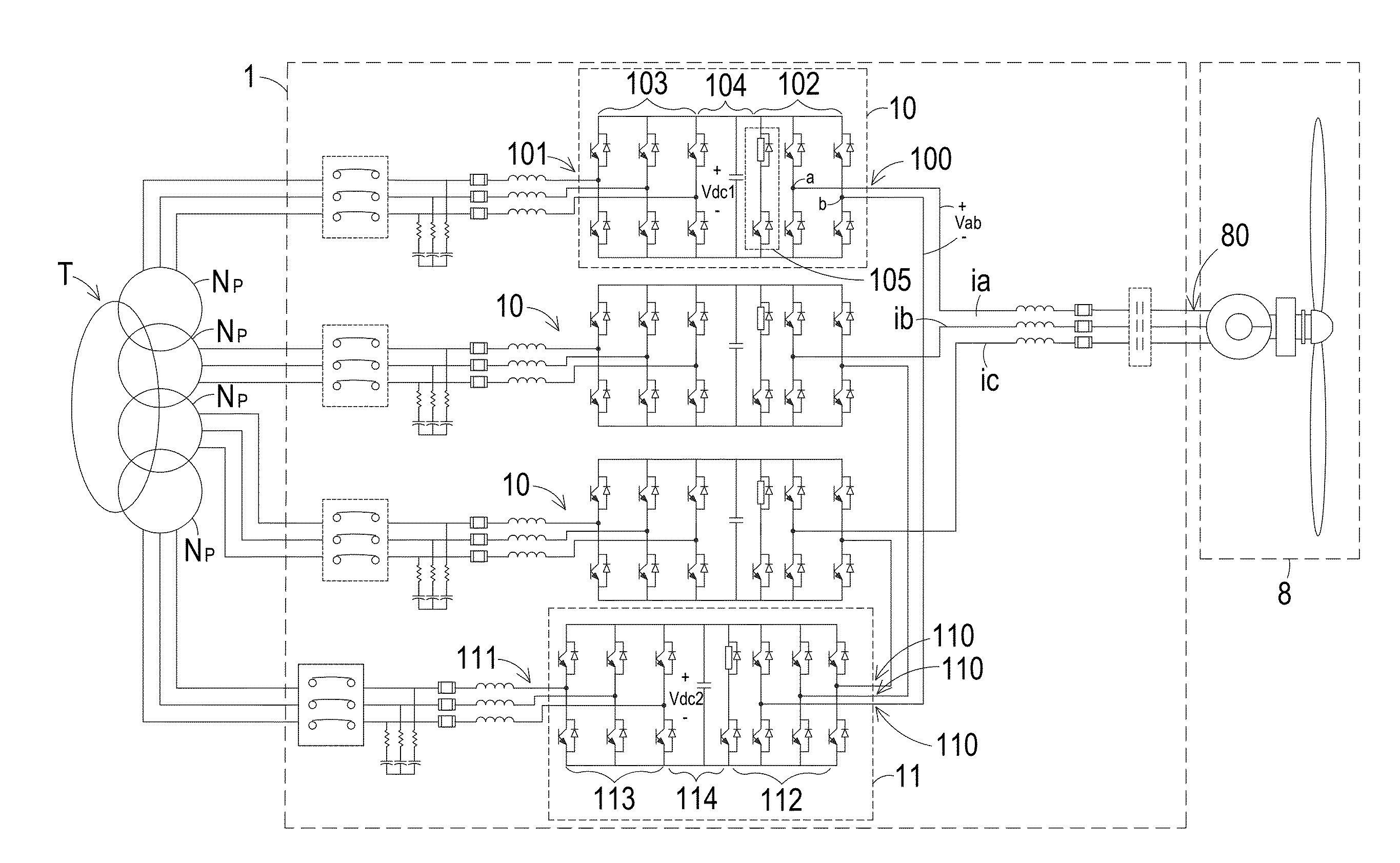
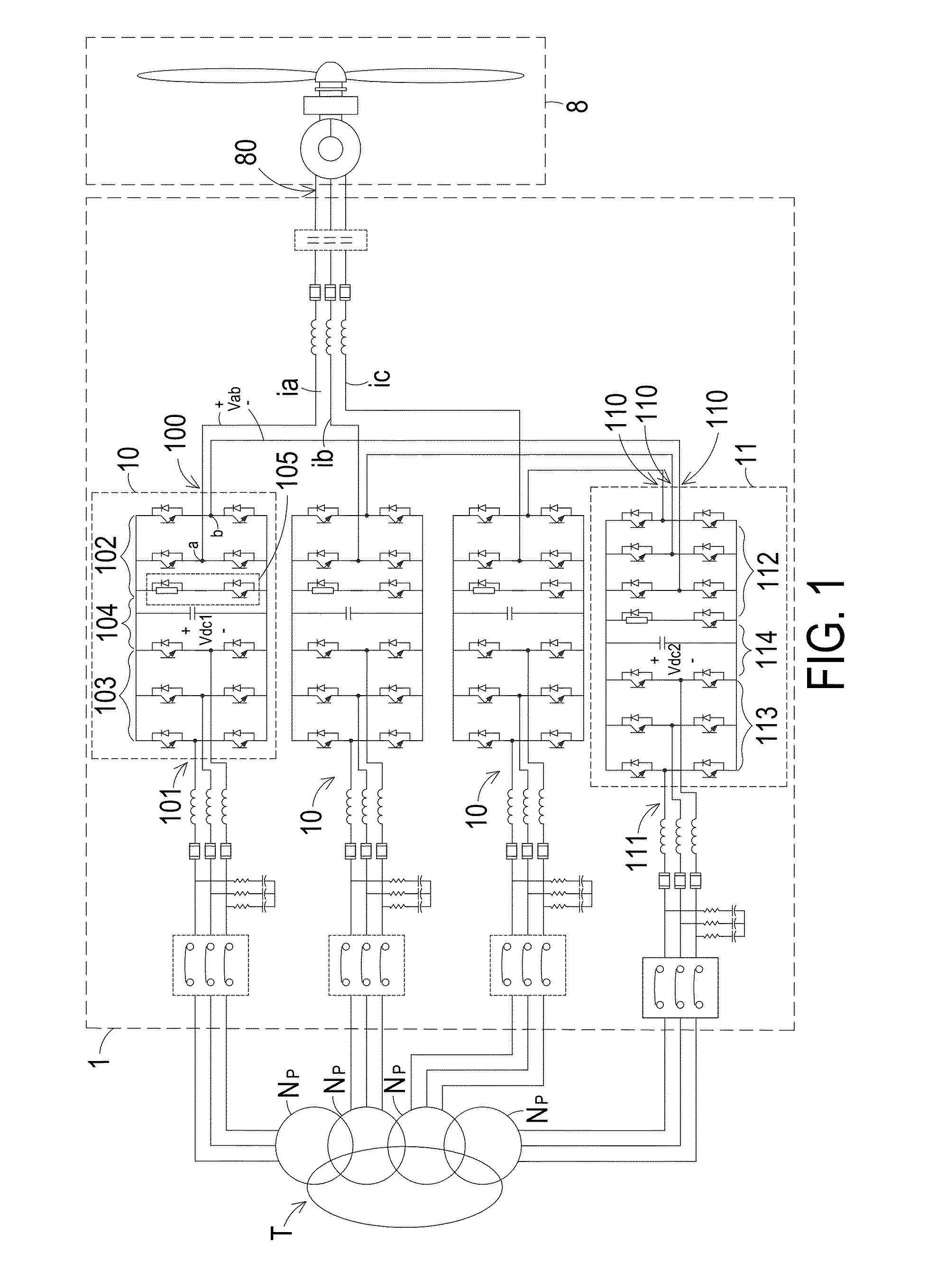
[0025]FIG. 1 is a schematic circuit diagram of a wind power conversion system according to the present invention. As shown in FIG. 1, the wind power conversion system 1 is electrically connected between a wind power generator 8 and an isolating transformer T. A primary side of the isolating transformer T is electrically connected with an AC power network. In this embodiment, the AC power from the wind power generator 8 may be converted by the wind power conversion system 1 and then transmitted to the AC power network through the isolating transformer T. Optionally, the AC power received by the isolating transformer T may be converted by the wind power conversion system 1 and then transmitted to the wind power generator 8. In other words, the wind power conversion system 1 may convert and transmit the electric energy in a single direction or bilateral directions.

[0026]In this embodiment, the voltage levels of the wind power generator 8 and the AC power network are medium voltage leve...

second embodiment

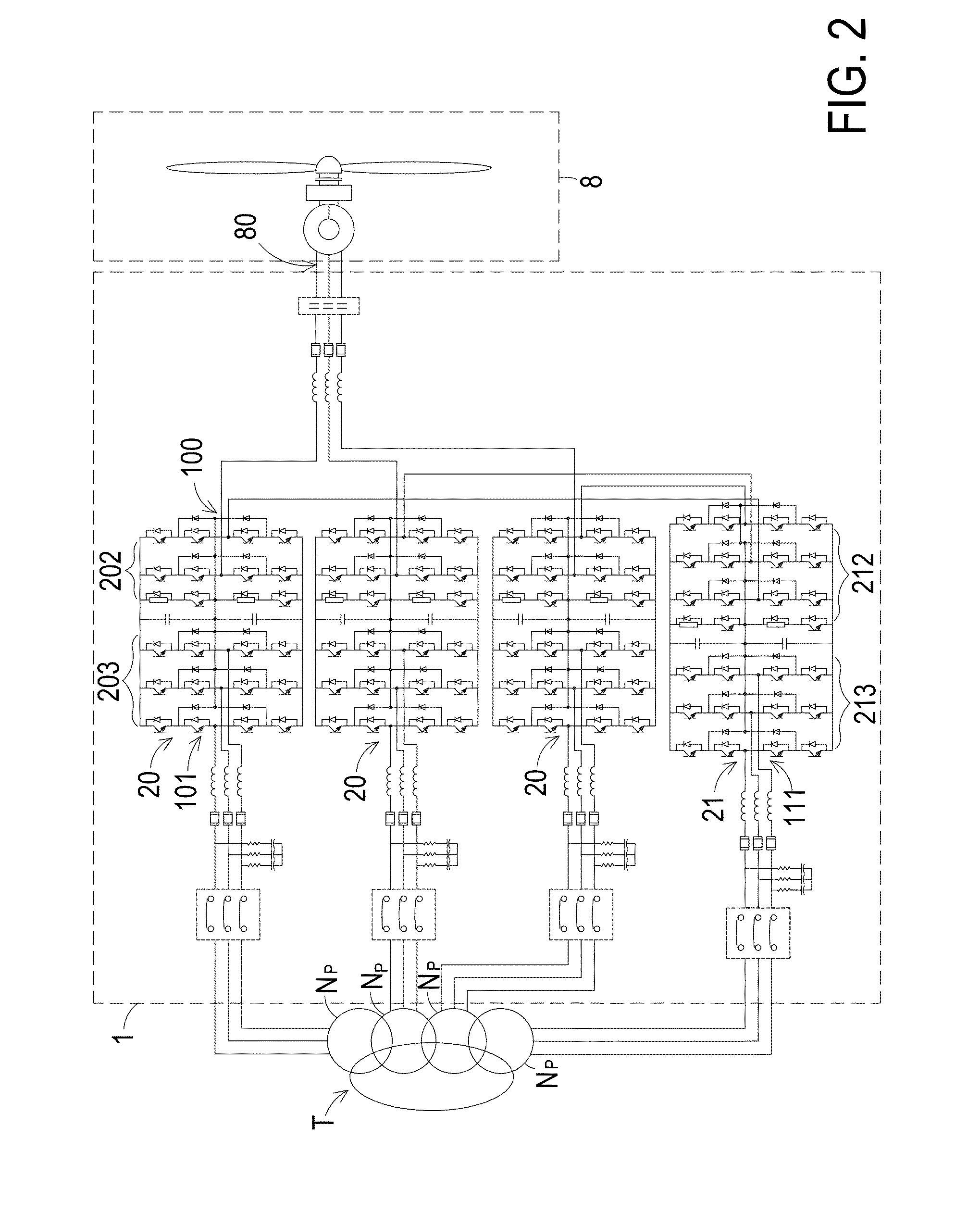
[0035]FIG. 2 is a schematic circuit diagram of a wind power conversion system according to the present invention. In comparison with FIG. 1, the first converting circuit 20 of the wind power conversion system 1 of this embodiment has a three-level circuitry configuration. The first generator-side converter 202 of the first converting circuit 20 has a single-phase full-bridge three-level circuitry configuration, and the first network-side converter 203 of the first converting circuit 20 has a three-phase three-level circuitry configuration. In comparison with FIG. 1, the second converting circuit 21 of the wind power conversion system 1 of this embodiment has a three-level circuitry configuration. The second generator-side converter 212 of the second converting circuit 21 has a three-phase full-bridge three-level circuitry configuration, and the second network-side converter 213 of the second converting circuit 21 has a three-phase three-level circuitry configuration.

third embodiment

[0036]FIG. 3 is a schematic circuit diagram of a wind power conversion system according to the present invention. In the embodiment of FIG. 1, the second converting circuit 11 has the AC / DC / AC circuitry configuration. In this embodiment, the second converting circuit 31 is a two stage matrix converting circuit. Consequently, the second converting circuit 31 has an AC / AC circuitry configuration. In this embodiment, the second converting circuit 31 comprises a second generator-side converter 312 and a second network-side converter 313, but the second DC bus storage unit 114 of FIG. 1 is omitted.


PUM


Abstract

A wind power conversion system includes plural first converting circuits and a second converting circuit. The plural first converting circuits perform a power converting task, and include respective first generator-side terminals and respective first network-side terminals. The first generator-side terminals are electrically connected with a wind power generator. The first network-side terminals are electrically connected with corresponding secondary windings of an isolating transformer. The second converting circuit includes plural second generator-side terminals and a second network-side terminal. The second network-side terminal is electrically connected with the corresponding secondary winding of plural secondary windings of the isolating transformer. The second generator-side terminals are serially connected with the corresponding first generator-side terminals of the first converting circuits. When the second converting circuit is enabled, the power converting task of the plural first converting circuits is shared by the second converting circuit.

Description

FIELD OF THE INVENTION[0001]The present invention relates to a wind power conversion system, and more particularly to a wind power conversion system that is easily controlled and cost-effective.BACKGROUND OF THE INVENTION[0002]Nowadays, the energy crisis problem becomes more serious. With increasing environmental consciousness, there are growing demands on renewable energy. For example, solar energy and wind power are the well-known power sources of the renewable energy. In the conventional renewable power generation system, the frequency and the amplitude of the AC power outputted by the power generator are different from the frequency and the amplitude of the AC power network. Consequently, a converting circuit is required to convert the AC power outputted by the power generator. By the converting circuit, the frequency and the amplitude of the AC power outputted by the power generator are identical to those of the AC power of the AC power network. Then, the converted AC power is ...

Claims


Application Information

Patent Timeline
IPC IPC(8): H02M5/458
CPCH02M5/458H02J3/386H02M7/49H02M5/4585H02J2300/28H02J3/381Y02B70/10Y02E10/72Y02E10/76H02J3/46H02M1/0032H02M7/25H02M1/32H02M1/0074
Inventor WANG, CHANGYONGCAI, LILU, YANSONGLU, FEI
Owner DELTA ELECTRONICS INC
Why Eureka
Try Eureka