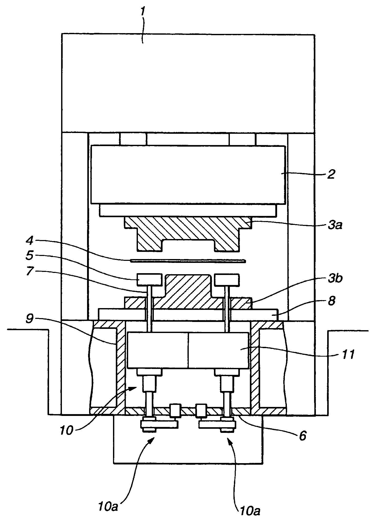
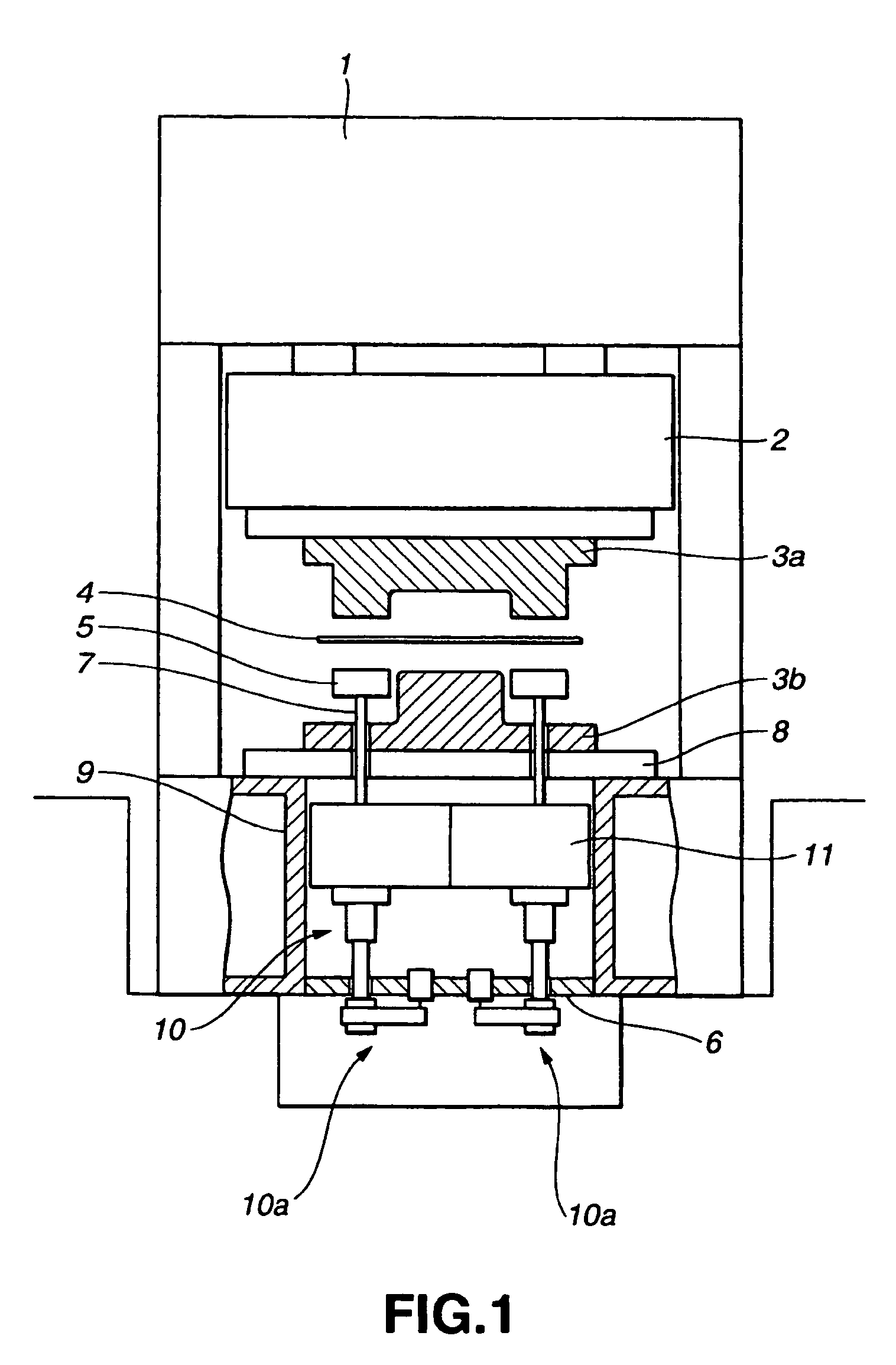
Die cushion device
a cushion and air pressure technology, applied in the direction of shock absorbers, forging presses, forging/pressing/hammering apparatuses, etc., can solve the problems of complex structure, maintenance and control, and the inability to control the pressure of the cushion using air pressure only, so as to achieve small friction loss, transmit high torque, and reduce the effect of friction loss
- Summary
- Abstract
- Description
- Claims
- Application Information
AI Technical Summary
Benefits of technology
Problems solved by technology
Method used
Image
Examples
first embodiment 1
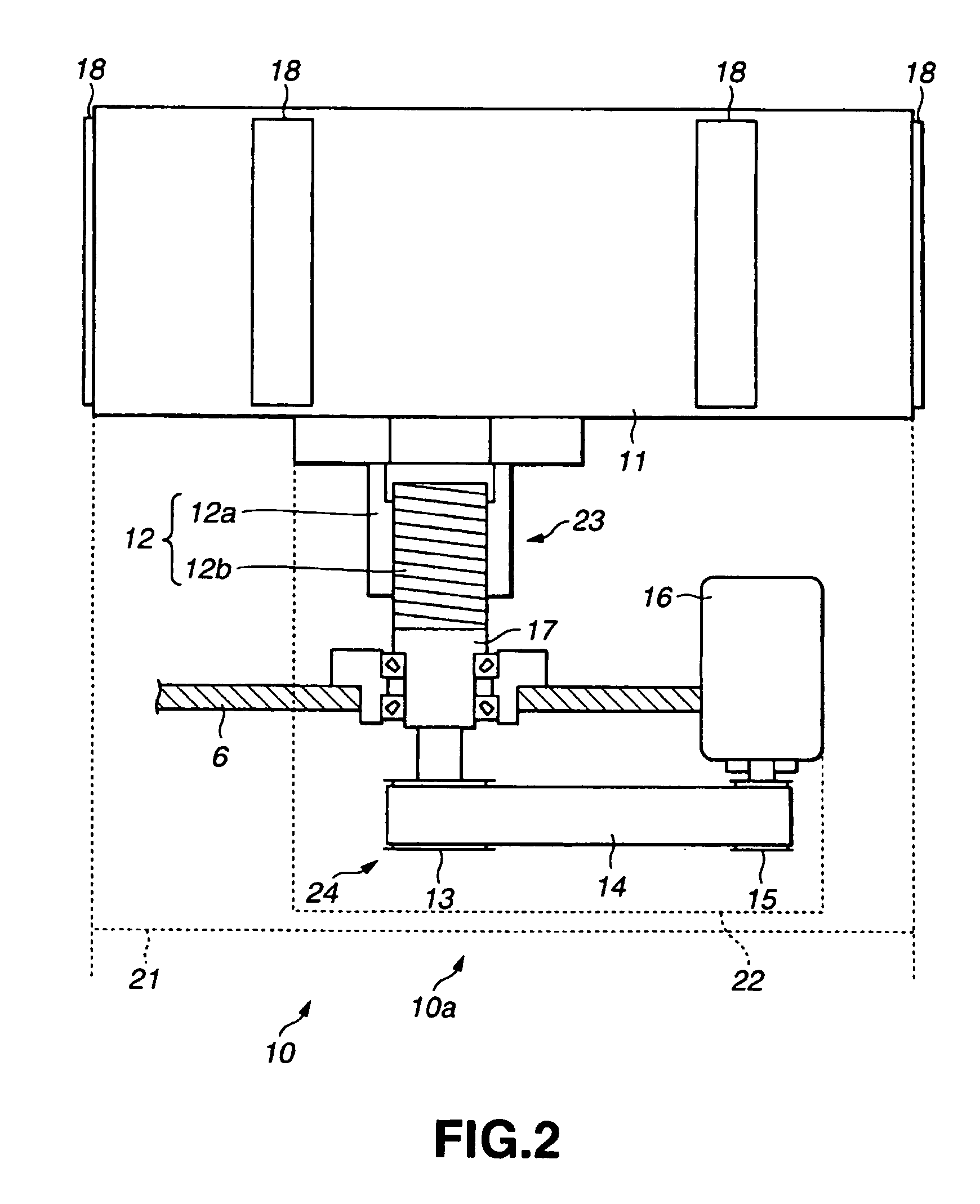
[0040]FIG. 2 is a schematic view of a die cushion according to a first embodiment.
[0041]In the die cushion module 10a, the cushion pad 11 is coupled to the rotation shaft of a servomotor 16 via a ball screw 12, a coupling member 22, a large pulley 13, a belt 14 and a small pulley 15. The power is mutually transferable between the cushion pad 11 and the servomotor 16. A nut portion 12a of the ball screw 12 is coupled to the bottom of the cushion pad 11. A thread portion 12b of the ball screw 12 is screwed into the nut portion 12a. The lower part of the thread portion 12b is connected to a coupling member 17. The coupling member 17 is rotatably supported in the beam 6 by a bearing or the like. And, its lower part is coupled to the large pulley 13. The small pulley 15 is connected to the rotation shaft of the servomotor 16. The belt 14 is wound around the large pulley 13 and the small pulley 15 to make the power transferable between them.
[0042]The rotary servomotor 16 has a rotation sh...
second embodiment
[0058]The structure of a second embodiment has many points which agree with those of the structure of the first embodiment. But, the nut side of the ball screw rotates and the thread side moves linearly in the first embodiment, but the thread side of the ball screw rotates and the nut side moves linearly in the second embodiment.
[0059]FIG. 7 is a schematic view of the die cushion according to the second embodiment.
[0060]In a die cushion module 40a, the cushion pad 11 is coupled to the rotation shaft of the servomotor 16 via a ball screw 42, a coupling member 47, the large pulley 13, the belt 14 and the small pulley 15. The power is mutually transferable between the cushion pad 11 and the servomotor 16. A thread portion 42b of the ball screw 42 is coupled to the lower part of the cushion pad 11. The thread portion 42b of the ball screw 42 is screwed into a nut portion 42a. The lower part of the nut portion 42b is connected to the coupling member 47. The coupling member 47 is rotatabl...
third embodiment
[0069]FIG. 8 is a schematic view of the die cushion according to a third embodiment.
[0070]In a die cushion module 60a, the cushion pad 11 is coupled to the rotation shaft of the servomotor 16 via a plunger rod 63, a piston 64, a ball screw 62, a coupling member 65, the large pulley 13, the belt 14 and the small pulley 15. The power is mutually transferable between the cushion pad 11 and the servomotor 16.
[0071]The columnar plunger rod 63 is connected to the lower part of the cushion pad 11. The plunger rod 63 is slidably supported its side surface by a cylindrical plunger guide 66. The plunger guide 66 is attachable to the beam 6. When the plunger guide 66 is fixed to the beam 6, the plunger rod 63 moves up and down while being supported by the plunger guide 66. The plunger guide 66 guides the plunger rod 63 and the cushion pad 11 which is coupled to the plunger rod 63 in the up and down directions.
[0072]A cylinder 63a which has an opening downward is formed in a lower part of the p...
PUM
| Property | Measurement | Unit |
|---|---|---|
| pressure | aaaaa | aaaaa |
| hydraulic pressure | aaaaa | aaaaa |
| air pressure | aaaaa | aaaaa |
Abstract
Description
Claims
Application Information
 - R&D
- Intellectual Property
- Life Sciences
- Materials
- Tech Scout
- Unparalleled Data Quality
- Higher Quality Content
- 60% Fewer Hallucinations
Browse by: Latest US Patents, China's latest patents, Technical Efficacy Thesaurus, Application Domain, Technology Topic, Popular Technical Reports.
© 2025 PatSnap. All rights reserved.Legal|Privacy policy|Modern Slavery Act Transparency Statement|Sitemap|About US| Contact US: help@patsnap.com


