
Die cushion device

a cushion and air pressure technology, applied in the direction of shock absorbers, forging presses, manufacturing tools, etc., can solve the problems of complex structure, maintenance and control, and the inability to accurately control the cushion pressure using air pressure, etc., to achieve small size with ease, large friction loss, and high torque transmission

Active Publication Date: 2005-12-22
KOMATSU LTD +1
View PDF2 Cites 2 Cited by
  • Summary
  • Abstract
  • Description
  • Claims
  • Application Information

AI Technical Summary

Benefits of technology

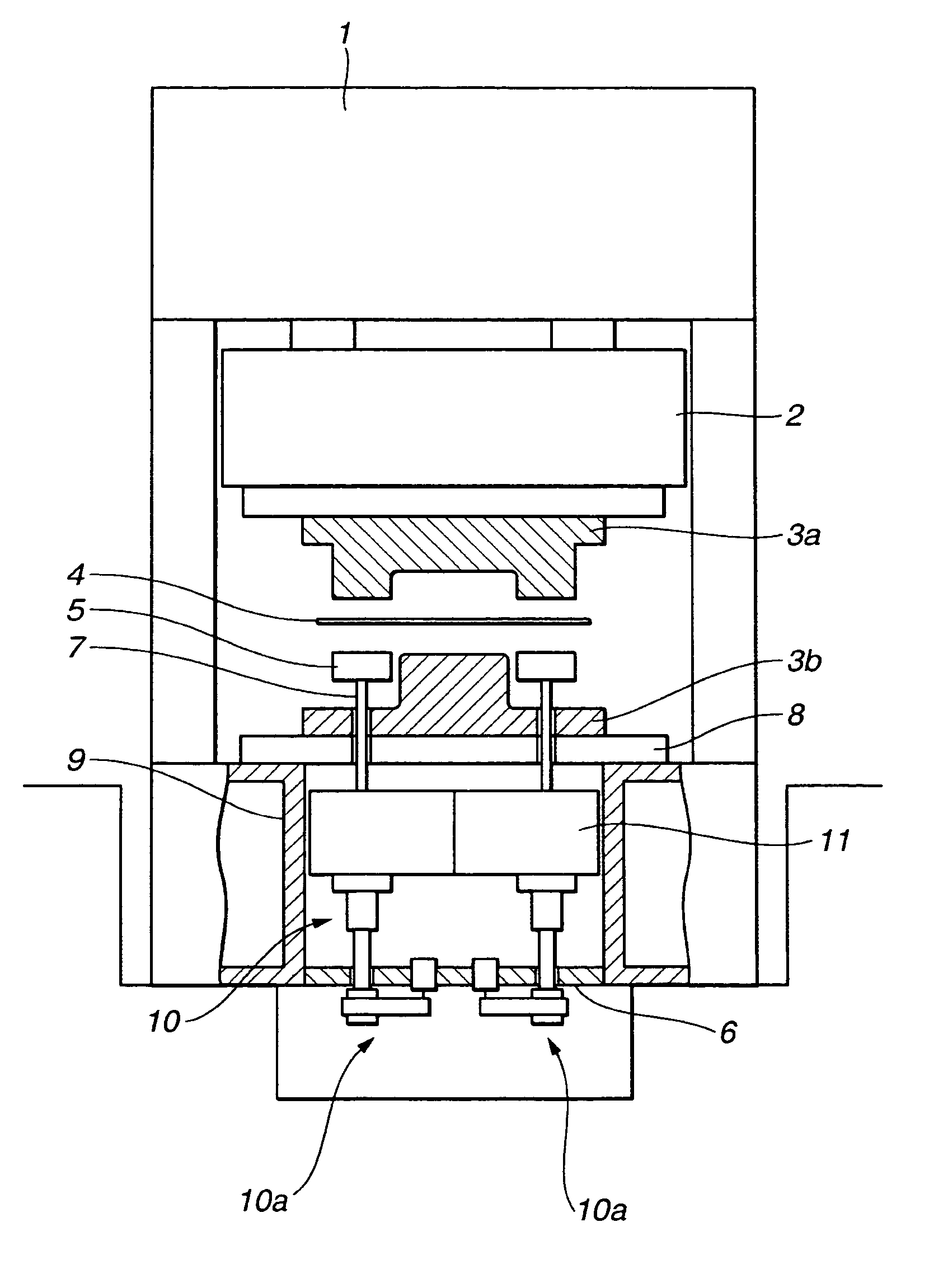
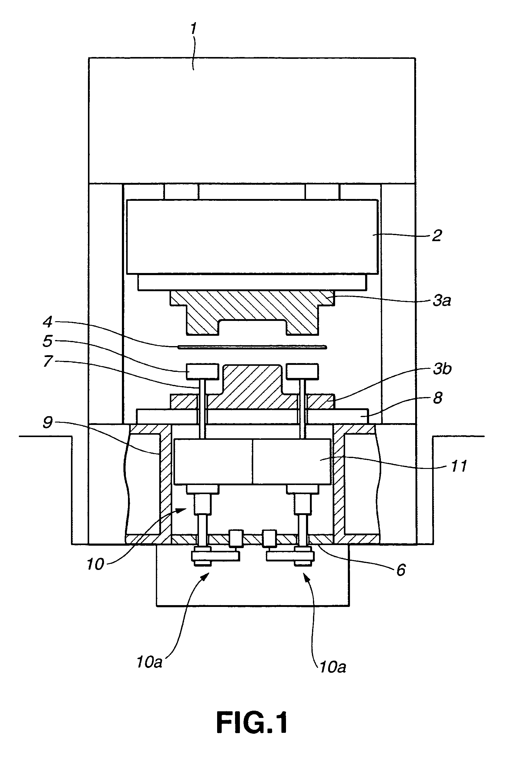
[0016] According to the first aspect of the present invention, the die cushion device is comprised of the die cushion modules which are independently drivable and unitized. The individual die cushion modules are provided with the cushion pad, the servomotor, the power transmission mechanism, the power conversion mechanism and the guide member. By configuring in this way, the die cushion of one working station comprises a combination of the die cushion modules which are standardized units. Where the die cushion is designed, the die cushion modules may be combined simply. In case of an engineering change, the combination can be changed simply to comply with the change. Thus, the design of the die cushion is facilitated by virtue of the die cushion modules, and the number of man-hours to design is decreased.
[0017] The capacity of the die cushion module is arbitrary. Therefore, when the capacity of the die cushion module is decreased, the drive mechanism becomes small, and the number of types of parts used is decreased. Meanwhile, the die cushion with a high capacity can be formed by combining plural small-capacity die cushion modules. In other words, the die cushion with a high capacity can be realized by the die cushion modules having a small drive mechanism. Thus, the number of type of parts is decreased by using the die cushion modules, and the parts management cost is reduced.
[0020] According to the second aspect of the present invention, all projected images of the servomotor, the power conversion mechanism and the power transmission mechanism are included in the projected image of the cushion pad which is presumed when projected from vertically above to a lower horizontal surface. By configuring in this way, the housing area of the drive mechanism in the horizontal direction does not become larger than the top surface area of the cushion pad. Therefore, the die cushion modules can be combined without suffering from the influence of the drive mechanism, and the flexibility of the die cushion is increased.
[0022] According to the third aspect of the invention, where the plural die cushion modules are combined, there is provided the rib which is provided between the opposed wall surfaces of the one working station of the bed. The individual cushion pads are housed into the spaces which are partly divided by the individual ribs and beds. Therefore, the cushion pads are adjacent to each other with the rib between them. By configuring in this way, the cushion pad becomes absent above the rib. Therefore, it is desirable to dispose a size larger top plate on the top surface of the cushion pad to cover the top of the rib. When the rib is provided, a warp of a cushion plate which is disposed on the top surface of the cushion pad can be reduced.
[0025] The ball screw mechanism has the center of axis of a rotation member and the center of axis of an up-and down member on the same axis, so that the projected images of the servomotor, the power conversion mechanism and the power transmission mechanism which are presumed when projected from vertically above to a lower horizontal surface can be made small with ease.
[0026] It is assumed that a screw and nut mechanism is included in the ball screw mechanism because it is comprised of the nut portion and the thread portion. The ball screw mechanism does not have a large friction loss, the screw and nut mechanism using a trapezoidal screw thread can transmit high torque, and the screw and nut mechanism using a triangular screw thread has an intermediate effect between them.

Problems solved by technology

The die cushion using an air pressure only cannot control the cushion pressure very accurately when the cushion pad operates.
But, the hydraulic equipment has drawbacks that its structure is complex, and precise maintenance and control are required.
And, it is natural to change a design of a drive mechanism depending on a limitation of *a mounting space* of the cushion pad and the press machine, and there are many occasions that the engineering change to the bed frame is forced.
Besides, a high capacity die cushion requires a large drive mechanism.
Then, types of used parts increase, then it becomes necessary to manage the various parts, and the management cost increases.
As described above, the production of a conventional die cushion may have problems that the number of man-hours to design increases and the cost becomes high.

Method used


Image

  • Die cushion device
  • Die cushion device
  • Die cushion device

Examples


first embodiment 1

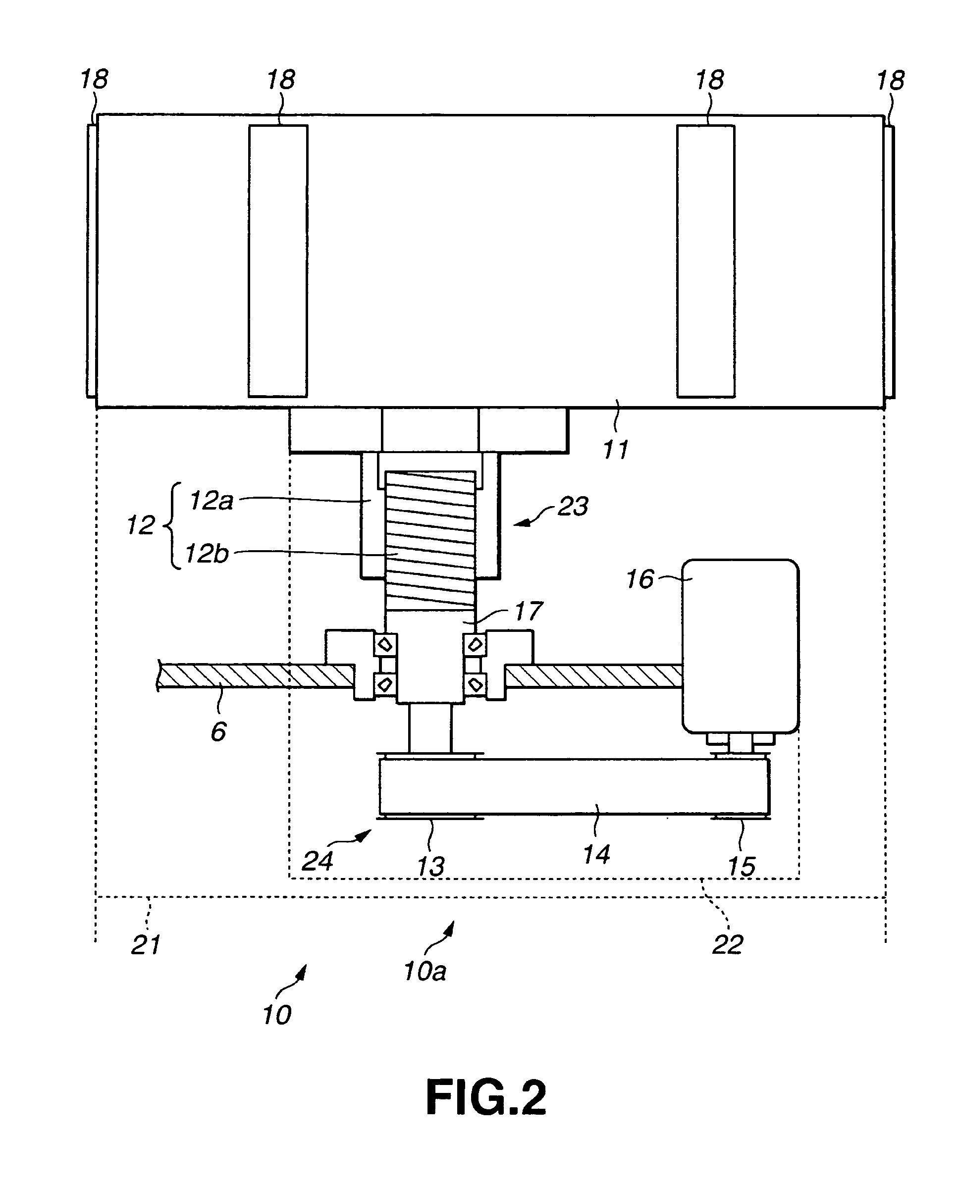
[0040]FIG. 2 is a schematic view of a die cushion according to a first embodiment.

[0041] In the die cushion module 10a, the cushion pad 11 is coupled to the rotation shaft of a servomotor 16 via a ball screw 12, a coupling member 22, a large pulley 13, a belt 14 and a small pulley 15. The power is mutually transferable between the cushion pad 11 and the servomotor 16. A nut portion 12a of the ball screw 12 is coupled to the bottom of the cushion pad 11. A thread portion 12b of the ball screw 12 is screwed into the nut portion 12a. The lower part of the thread portion 12b is connected to a coupling member 17. The coupling member 17 is rotatably supported in the beam 6 by a bearing or the like. And, its lower part is coupled to the large pulley 13. The small pulley 15 is connected to the rotation shaft of the servomotor 16. The belt 14 is wound around the large pulley 13 and the small pulley 15 to make the power transferable between them.

[0042] The rotary servomotor 16 has a rotatio...

second embodiment

[0058] The structure of a second embodiment has many points which agree with those of the structure of the first embodiment. But, the nut side of the ball screw rotates and the thread side moves linearly in the first embodiment, but the thread side of the ball screw rotates and the nut side moves linearly in the second embodiment.

[0059]FIG. 7 is a schematic view of the die cushion according to the second embodiment.

[0060] In a die cushion module 40a, the cushion pad 11 is coupled to the rotation shaft of the servomotor 16 via a ball screw 42, a coupling member 47, the large pulley 13, the belt 14 and the small pulley 15. The power is mutually transferable between the cushion pad 11 and the servomotor 16. A thread portion 42b of the ball screw 42 is coupled to the lower part of the cushion pad 11. The thread portion 42b of the ball screw 42 is screwed into a nut portion 42a. The lower part of the nut portion 42b is connected to the coupling member 47. The coupling member 47 is rota...

third embodiment

[0069]FIG. 8 is a schematic view of the die cushion according to a third embodiment.

[0070] In a die cushion module 60a, the cushion pad 11 is coupled to the rotation shaft of the servomotor 16 via a plunger rod 63, a piston 64, a ball screw 62, a coupling member 65, the large pulley 13, the belt 14 and the small pulley 15. The power is mutually transferable between the cushion pad 11 and the servomotor 16.

[0071] The columnar plunger rod 63 is connected to the lower part of the cushion pad 11. The plunger rod 63 is slidably supported its side surface by a cylindrical plunger guide 66. The plunger guide 66 is attachable to the beam 6. When the plunger guide 66 is fixed to the beam 6, the plunger rod 63 moves up and down while being supported by the plunger guide 66. The plunger guide 66 guides the plunger rod 63 and the cushion pad 11 which is coupled to the plunger rod 63 in the up and down directions.

[0072] A cylinder 63a which has an opening downward is formed in a lower part of...


PUM


Abstract

A die cushion device is comprised of die cushion modules which are independently movable and unitized. The individual die cushion modules are provided with a cushion pad, a servomotor, a power transmission mechanism, a power conversion mechanism and a guide member. By configuring in this way, the design of the die cushion is facilitated, a drive mechanism of the die cushion becomes compact, and the number of types of parts used is decreased.

Description

BACKGROUND OF THE INVENTION [0001] 1. Field of the Invention [0002] The present invention relates to a die cushion device of a press machine which drives up and down a cushion pad by a servomotor. [0003] 2. Description of the Related Art [0004] The press machine is provided with a die cushion device (hereinafter simply called as the die cushion) which is used to suppress wrinkles during drawing. A conventional die cushion produces a cushion pressure while driving up and down a cushion pad by using a hydraulic pressure or an air pressure. To enhance drawability of the press machine and to prevent a work from being broken or distorted, it is necessary to control the cushion pressure of the die cushion with high accuracy, especially it is necessary to control the cushion pressure with high accuracy when the cushion pad is moved downward. [0005] The die cushion using an air pressure only cannot control the cushion pressure very accurately when the cushion pad operates. The die cushion u...

Claims


Application Information

Patent Timeline
IPC IPC(8): B21D22/21B21D24/02B21D24/08
CPCB21D24/08
Inventor SHIROZA, KAZUHIKOTAKAYAMA, YUKIYOSHIHONMA, HIROAKISEKI, SEIJI
Owner KOMATSU LTD
Learn More