
Device and method for sanitizing gas and water

a technology for sanitizing gas and water, applied in boring tools, water/sludge/sewage treatment, specific water treatment objectives, etc., can solve the problems of microorganism build-up, microorganism build-up, biofilm, etc., to prevent build-up and/or reduce biofilm pathogens, prevent the effect of reducing biofilm pathogens

Inactive Publication Date: 2016-07-28
KIREMITCI KIRKOR
View PDF11 Cites 3 Cited by
  • Summary
  • Abstract
  • Description
  • Claims
  • Application Information

AI Technical Summary

Benefits of technology

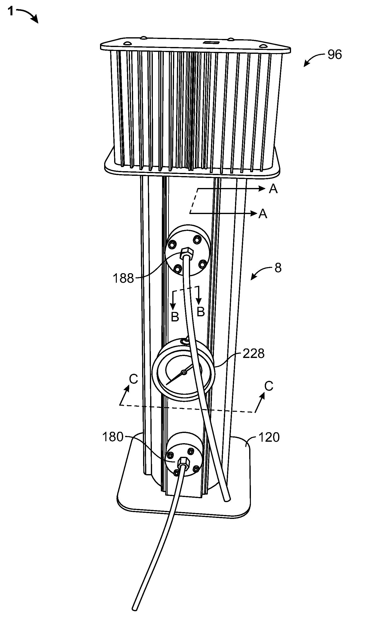
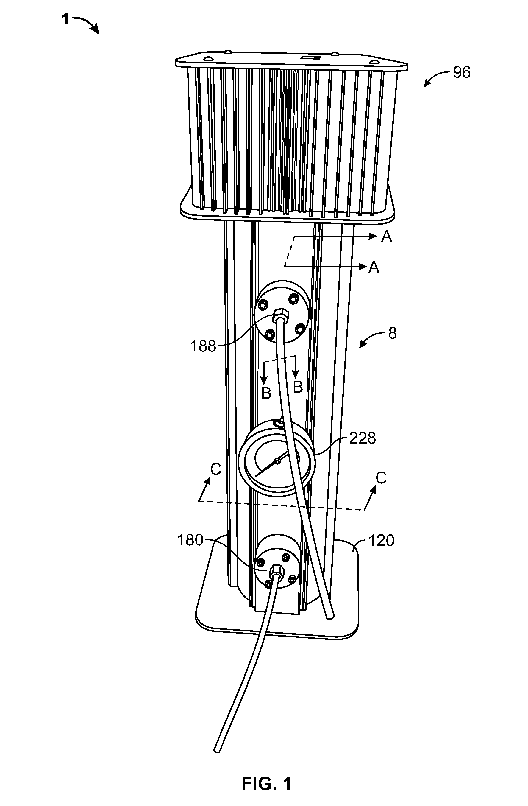
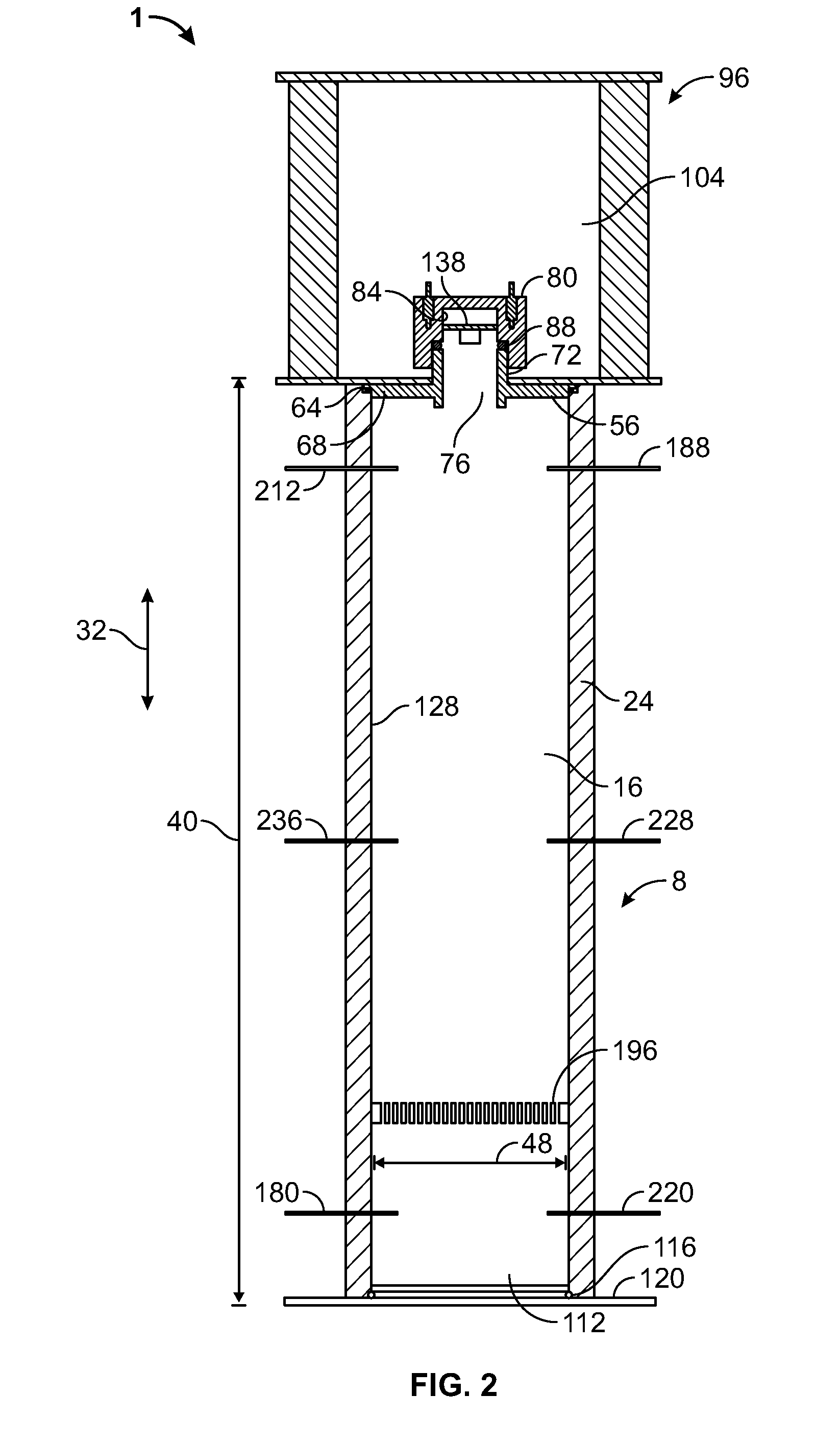
The patent describes devices that use light to sanitize medical gas, water, and fluid by removing biofilm pathogens. These devices prevent buildup and reduce harmful microorganisms that can cause infections during medical procedures. The devices include a housing with a sanitizing chamber, a light source, a water conduit, and a gas conduit through which the sanitized gas flows. The devices can also have a recirculation system with a pump, sensor, and check valve to ensure constant sanitization. Overall, the devices help to create safer environments for medical procedures and dental treatments.

Problems solved by technology

Furthermore, microorganisms may build up over time, creating, for example, biofilm in the water line for transporting water from the water source to the water-based tool.
Moreover, like water systems, microorganisms, such as in a biofilm, may build up over time in the gas line for transport from the gas source to the gas-based tool.
Even where filters perform adequately, the gas line may represent a potential source of microorganisms.
A drying system may be further provided in a gas system, which may further cause build-up of microorganisms, such as biofilm, in the gas transport system.

Method used


Image

  • Device and method for sanitizing gas and water
  • Device and method for sanitizing gas and water
  • Device and method for sanitizing gas and water

Examples


Embodiment Construction

[0032]Various apparatuses or processes will be described below to provide an example of each claimed embodiment. No embodiment described below limits any claimed embodiment and any claimed embodiment may cover processes or apparatuses that differ from those described below. The claimed embodiments are not limited to apparatuses or processes having all of the features of any one apparatus or process described below or to features common to multiple or all of the apparatuses described below. It is possible that an apparatus or process described below is not covered by any of the claimed embodiments. Any embodiment disclosed below that is not claimed in this document may be the subject matter of another protective instrument, for example, a continuing patent application, and the applicants, inventors or owners do not intend to abandon, disclaim or dedicate to the public any such embodiment by its disclosure in this document.

[0033]According to various exemplary devices described herein,...


PUM

PropertyMeasurementUnit
lengthaaaaaaaaaa
wavelengthsaaaaaaaaaa

Abstract

A device for preventing build up and / or reducing biofilm pathogens from medical or dental fluids includes a housing defining a sanitizing chamber. A water conduit may extend through the sanitizing chamber and channel water from a water inlet to a water outlet. A gas inlet may receive pressurized gas and gas outlet may flow the pressurized gas from the inlet to the gas outlet through the sanitizing chamber. A light source emits light into the sanitizing chamber, the emitted light being incident on the water conduit and / or the pressurized gas in the sanitizing chamber and having wavelengths effective for removing biofilm pathogens from the water and / or the pressurized gas to sanitize the water and the pressurized gas. The sanitized water and gas may be used when performing medical or dental procedures. The device may further include a recirculation system for recirculating water from the water outlet to the water inlet.

Description

TECHNICAL FIELD[0001]The present subject-matter relates to devices and methods for sanitizing gas and water, and more particularly to devices and methods for sanitizing gas and water within a sanitizing chamber.INTRODUCTION[0002]Various fields make use of a source of water and / or a source of gas. Tools used in such fields may be powered by water from the source of water or gas from the source of gas. Tools used may also dispense water and / or gas. Such fields may include the medical fields and dental field, where the water and / or gas may be used or dispensed when performing various dental or medical procedures.[0003]The source of water may be stored or treated and fed to a water-based tool via a water line. The storage mechanism or treating mechanism may be located in a location that is remote of the location of the water-based tool. In some situations, the water line may have a substantial length.[0004]Similarly, the source of gas may be stored or treated and is fed to the gas-based...

Claims


Application Information

Patent Timeline
Patent Type & Authority Applications(United States)
IPC IPC(8): A61C1/00C02F1/32A61L2/10
CPCA61C1/0076A61L2/10C02F2303/04A61C1/0092C02F2103/006C02F1/32C02F1/325C02F1/78C02F2103/026C02F2201/3222C02F2201/3223C02F2201/3227C02F2201/326B01D53/007B01D2259/804
Inventor KIREMITCI, KIRKOR
Owner KIREMITCI KIRKOR
Learn More