
Machine vision robotic stud welder

a robot and stud welding technology, applied in the direction of soldering apparatus, welding devices, manufacturing tools, etc., can solve the problems of increasing construction time and cost, frequent worker injuries, and slow and arduous

Active Publication Date: 2016-07-28
STRUCTURAL SERVICES
View PDF17 Cites 12 Cited by
  • Summary
  • Abstract
  • Description
  • Claims
  • Application Information

AI Technical Summary

Benefits of technology

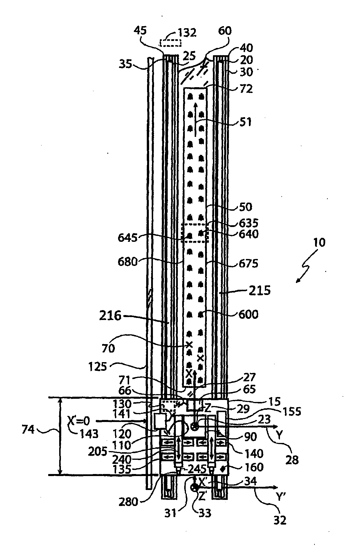
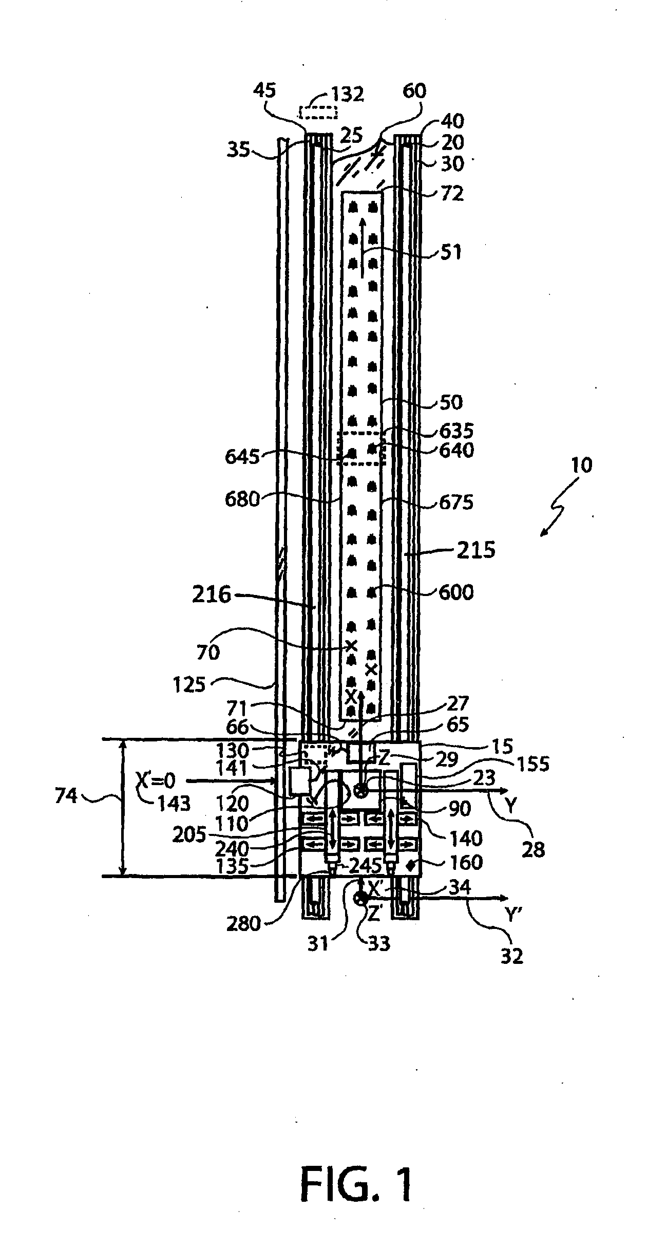
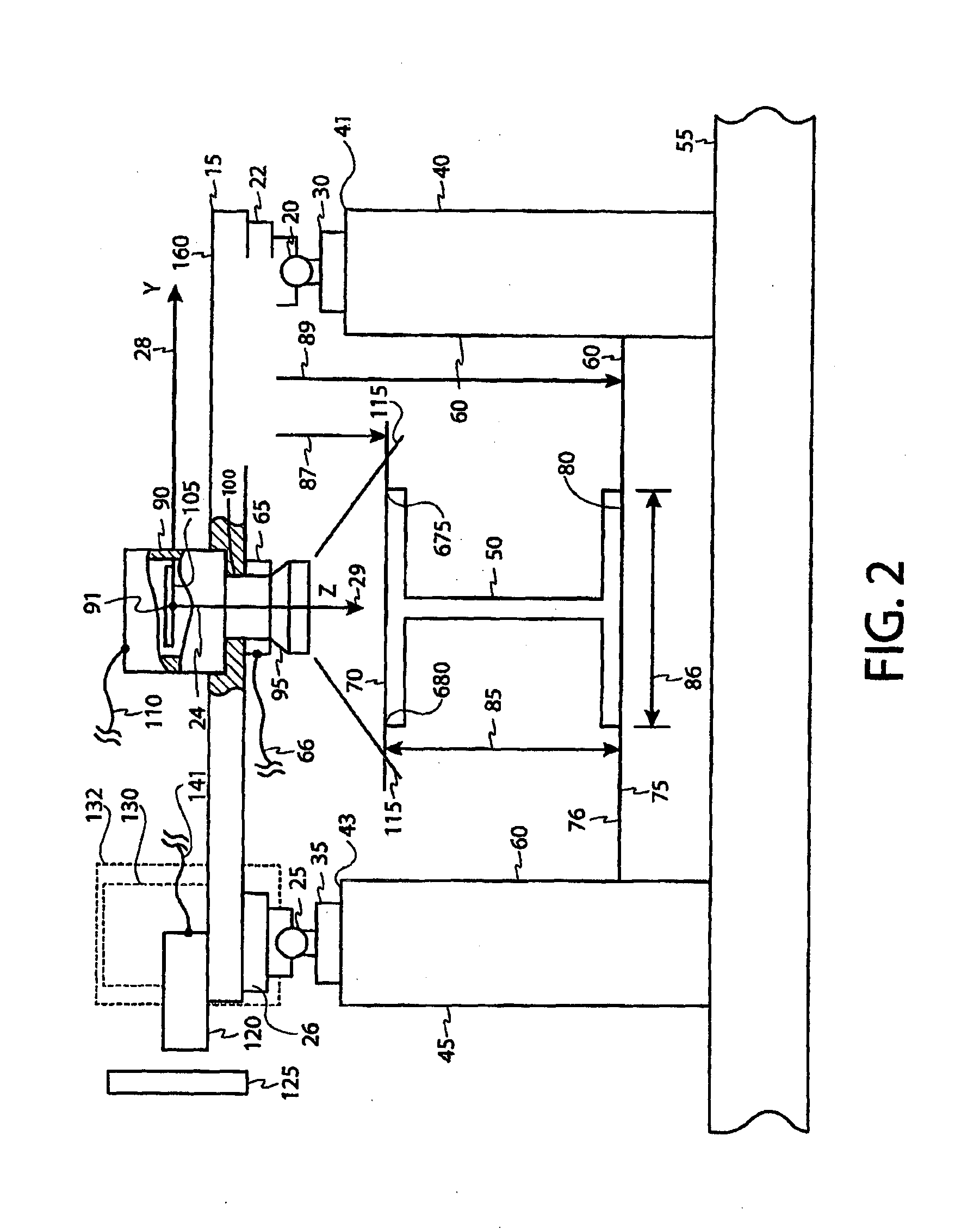
The invention is an apparatus and method for automatically welding studs on a beam surface. The apparatus includes a carriage, an imager, and a welding assembly. The imager captures images of the beam surface as the carriage moves, and the computer identifies pre-marked welding sites and determines their location relative to the carriage and welding assembly. The welding assembly then places and welds a stud on the beam surface at the pre-marked welding site. The technical effects of the invention include improved accuracy in identifying and positioning welding sites, reduced labor requirements, and improved efficiency in the welding process.

Problems solved by technology

This is a slow and arduous process that requires the worker to repeatedly bend over in order to first place the stud within a pre-positioned ferrule over a ground welding site on the beam, and then to weld the stud into place on the beam.
The slow speed of this process increases construction time and costs, and leads to frequent worker injuries.

Method used


Image

  • Machine vision robotic stud welder
  • Machine vision robotic stud welder
  • Machine vision robotic stud welder

Examples


second embodiment

[0239]Referring now to FIGS. 14 and 15, a robotic welding system 1300 is shown resting on surface 1303 of corrugated steel support structure 1308, positioned above and longitudinally aligned over I-beam 1302. In this embodiment, the welding system 1300 is tractor-propelled. Corrugated structure 1308 has been previously attached to top surface 1304 of beam 1302. Top surface 1304 has further ground welding sites 1306 where conventional studs may be welded by welding system 1300.

[0240]Welding system 1300 has rectangular frame 1350 which includes front and rear transverse frame members 1354 and 1353 respectively, and longitudinal right and left frame members 1351 and 1352 respectively. A conventional X-Y-Z right hand coordinate system 1484 is defined and located on the top surface and in the middle of front frame member 1354.

[0241]Welding system 1300 is propelled by conventional right and left tracks 1305 and 1310 respectively. Tracks 1305 and 1310 are identical and comprise individual ...

third embodiment

[0301]Referring now generally to FIGS. 19-29, a welding system 2010 in accordance with the present invention will now be described in detail. In this embodiment, the welding system 2010 is designed to ride alongside an I-beam 2001 to which studs are to be welded, as opposed to directly above the I-beam 2001 as shown in the embodiment of FIGS. 14-18. In this embodiment, the welding system 2010 comprises a tractor 2012 having a frame 2014 and a pair of tracks 2016a,2016b, each of which comprises a respective track shoe 2018a,2018b. The tracks 2016a,2016b are each operated by a respective one of a pair of hydraulic wheel motor 2017a,2017b (see FIGS. 19, 27, and 29). In this embodiment, the hydraulic wheel motors 2017a,2017b are Model No. PHK-1B hydraulic motors produced by Nachi America, Inc. of Greenwood, Ind., U.S.A., although other hydraulic motors would be suitable in alternate embodiments of the present invention. As shown in the embodiment of FIGS. 14 and 15, during use the track...


PUM

PropertyMeasurementUnit
Angleaaaaaaaaaa

Abstract

The present disclosure teaches systems and methods for robotic welding of studs onto the surface of I-beams. These systems and methods will find industrial applicability in, for example, the steel erection industry.

Description

FIELD OF THE INVENTION[0001]This present invention relates generally to arc-welding equipment for welding studs at predefined welding sites, and in particular to robotically-controlled stud welders which use machine vision to identify and locate a welding site on a surface of a beam or girder and which further automatically weld studs at these sites, and related methods therefor.BACKGROUND OF THE INVENTION[0002]In steel erection projects, for example road construction and bridge building, steel studs are typically manually placed onto the surfaces of steel beams into ceramic ferrules, and then are welded in place onto the beam. Conventional, manual techniques for feeding and aligning both studs and ferrules into collets are well known in the art and are disclosed, for example, in U.S. Pat. No. 5,130,510. This is a slow and arduous process that requires the worker to repeatedly bend over in order to first place the stud within a pre-positioned ferrule over a ground welding site on th...

Claims


Application Information

Patent Timeline
IPC IPC(8): B23K9/20B23K37/02B23K9/095
CPCB23K9/20B23K9/0953B23K37/0258B23K37/0282B23K9/0956B23K2103/04B23K26/08B23K26/1476B23K26/34B23K26/144
Inventor BENZING, JAMES T.HALLER, WILLIAM R.PATTERSON, JACOB B.
Owner STRUCTURAL SERVICES
Learn More