Wheel assemblies with non-pneumatic tires

Inactive Publication Date: 2016-07-28
MTD PRODUCTS
View PDF16 Cites 37 Cited by
  • Summary
  • Abstract
  • Description
  • Claims
  • Application Information

AI Technical Summary

Benefits of technology

[0008]The following presents a simplified summary in order to provide a basic understanding of some example aspects of the disclosure. This summary is not an extensive overview. Moreover, this summary is not intended to identify

Problems solved by technology

At times, these tires are damaged or otherwise caused to be deflated during shipment.
At other times, these tires may lose pressure after remaining in a single location for extended periods, such as a snow thrower stored in a shed during summer months.
This can lead to costly warr

Method used


Image

  • Wheel assemblies with non-pneumatic tires
  • Wheel assemblies with non-pneumatic tires
  • Wheel assemblies with non-pneumatic tires

Examples


Embodiment Construction

[0022]Example embodiments that incorporate one or more aspects of the present disclosure are described and illustrated in the drawings. These illustrated examples are not intended to be a limitation on the present disclosure. For example, one or more aspects of the present disclosure can be utilized in other embodiments and even other types of devices. Moreover, certain terminology is used herein for convenience only and is not to be taken as a limitation on the present disclosure. Still further, in the drawings, the same reference numerals are employed for designating the same elements.

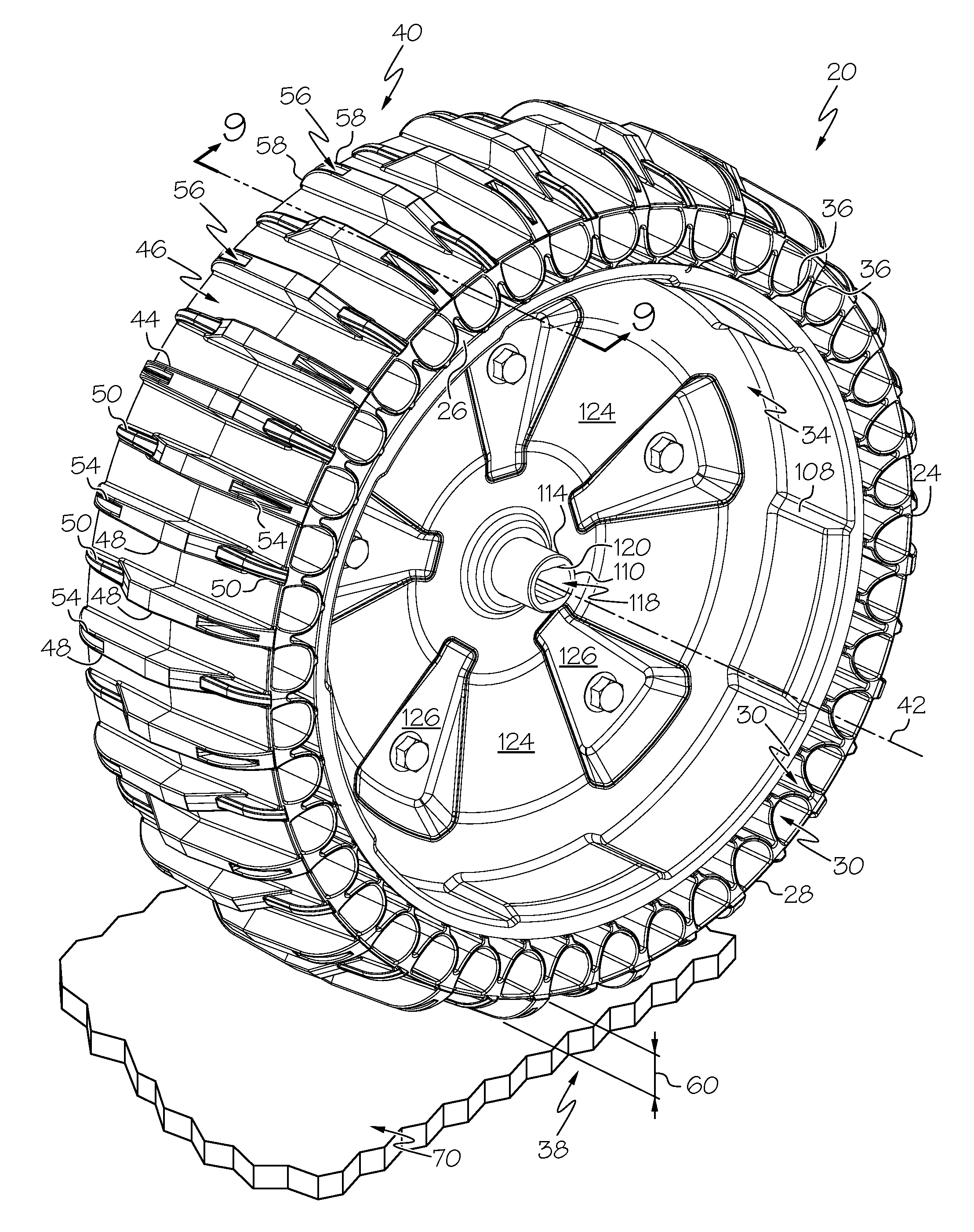
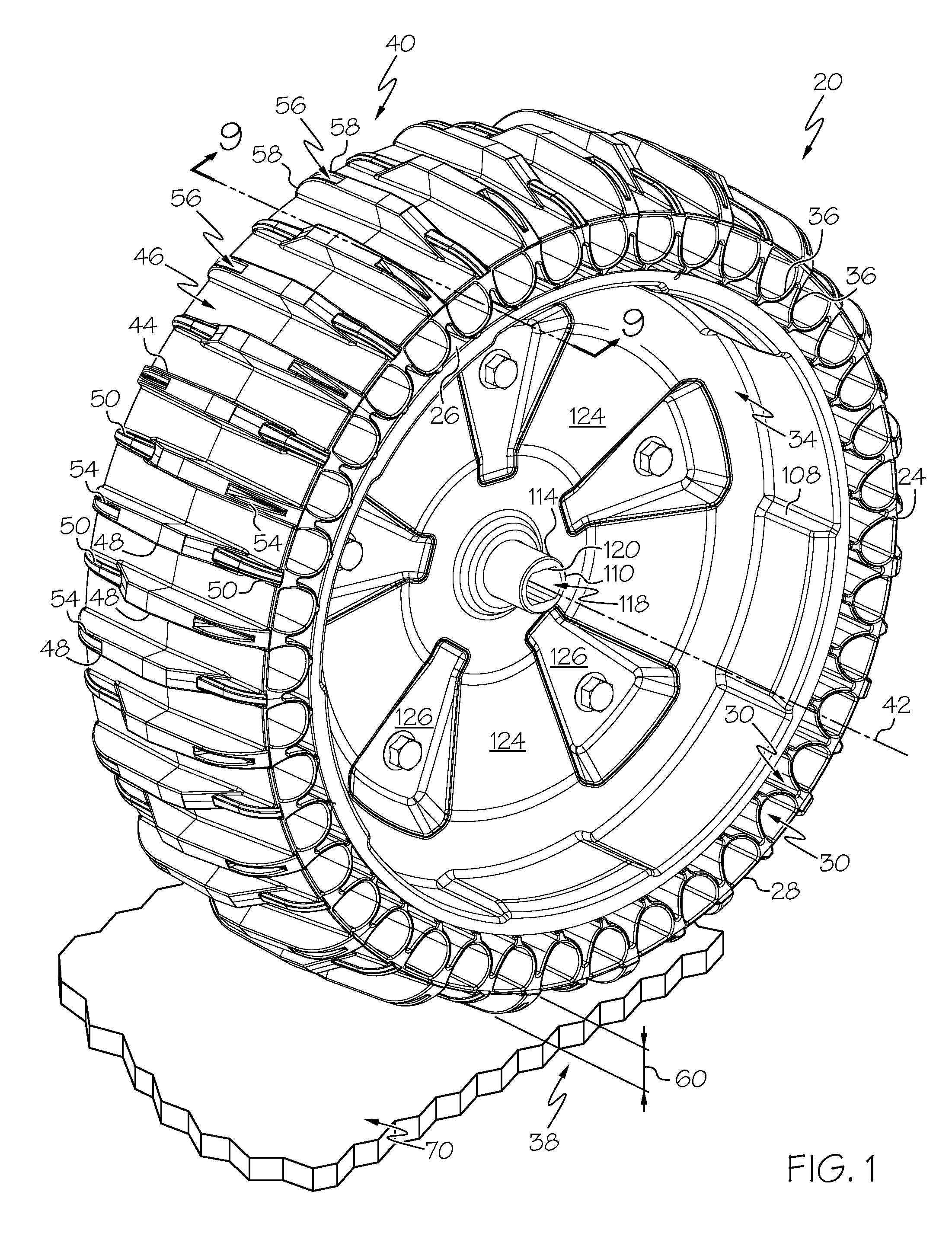
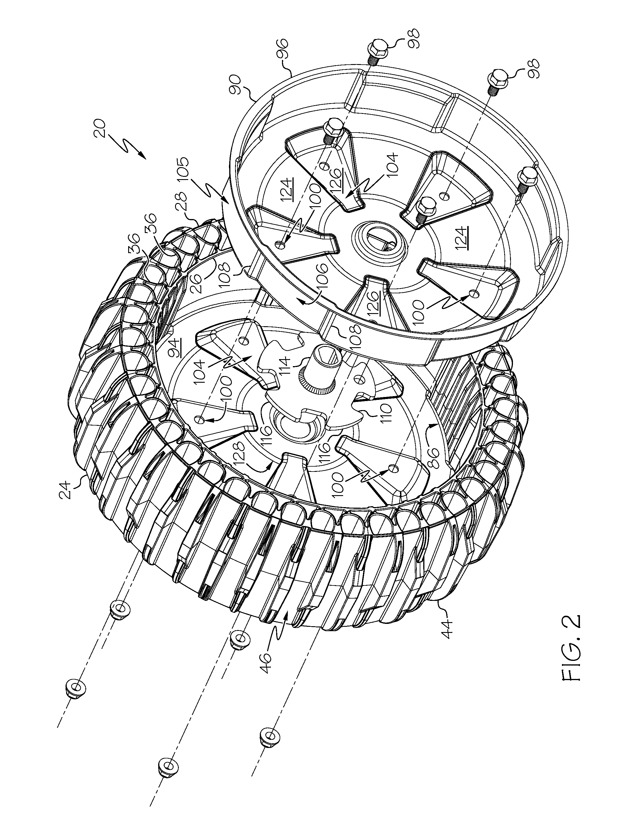
[0023]The described apparatus provides for a non-pneumatic tire and wheel configuration, herein called “non-pneumatic tire,” which can improve certain traction aspects while reducing the need for conventional service and maintenance. The non-pneumatic tire may be attached to both pedestrian or “walk-behind” and “riding” outdoor power equipment, including, but not limited to, walk-behind mowers and sn...


PUM


Abstract

A non-pneumatic tire assembly includes a non-pneumatic tire. The non-pneumatic tire includes an inner circumferential ring and an outer circumferential ring defining an annular space and a cylindrical space inside the inner circumferential ring. A plurality of partitions connect the circumferential rings within the annular space. A ground-contacting tread is located on the outer circumferential ring. A rim, including a plurality of pieces, is located within the cylindrical space. The non-pneumatic tire assembly further includes a hub that is removably connected to the rim.

Description

[0001]This application claims the benefit of U.S. Provisional Application No. 62 / 108,112, filed Jan. 27, 2015, the entire disclosure of which is hereby incorporated herein by reference.[0002]BACKGROUND[0003]1. Field of the Disclosure[0004]The present application is directed to a non-pneumatic tire and a wheel assembly using a non-pneumatic tire, and more particularly, to a non-pneumatic tire for outdoor power equipment.[0005]2. Description of Related Art[0006]Many outdoor power equipment devices are provided with pneumatic, or air-filled, tires made of an airtight inner core filled with pressurized gas. A tread, usually reinforced with steel belting or other materials, covers this inner core and provides an area which contacts the traction surface. At times, these tires are damaged or otherwise caused to be deflated during shipment. At other times, these tires may lose pressure after remaining in a single location for extended periods, such as a snow thrower stored in a shed during ...

Claims


Application Information

Patent Timeline
IPC IPC(8): B60C7/10B60C7/24
CPCB60C7/24B60C7/10B60C7/26B60B9/02B60B9/26B60B15/025B60B25/006B60C7/18B60C2011/0337B60C11/0311B60C7/107B60C7/146B60C7/143
Inventor SCHAEDLER, AXELBUCHANAN, PETER J.
Owner MTD PRODUCTS
Why Eureka
Try Eureka