Fuel injection control device of engine and fuel injection control method of engine

a technology of fuel injection control and control device, which is applied in the direction of electric control, combustion engines, machines/engines, etc., can solve the problems of fuel consumption performance deterioration and exhaust performan

Active Publication Date: 2016-07-28
NISSAN MOTOR CO LTD
View PDF11 Cites 2 Cited by
  • Summary
  • Abstract
  • Description
  • Claims
  • Application Information

AI Technical Summary

Benefits of technology

[0005]It is an object of the present invention to provide a fuel injection control device of an engine, capable of realizing optimum fuel injection to an engine operation state.

Problems solved by technology

According to the above-described fuel injection control device, optimum fuel injection with regard to an engine operation state cannot be made, and deterioration in fuel consumption performance and exhaust performance may be caused especially in a region where the fuel injection flow rate of the fuel injection valve is low.

Method used


Image

  • Fuel injection control device of engine and fuel injection control method of engine
  • Fuel injection control device of engine and fuel injection control method of engine
  • Fuel injection control device of engine and fuel injection control method of engine

Examples


Embodiment Construction

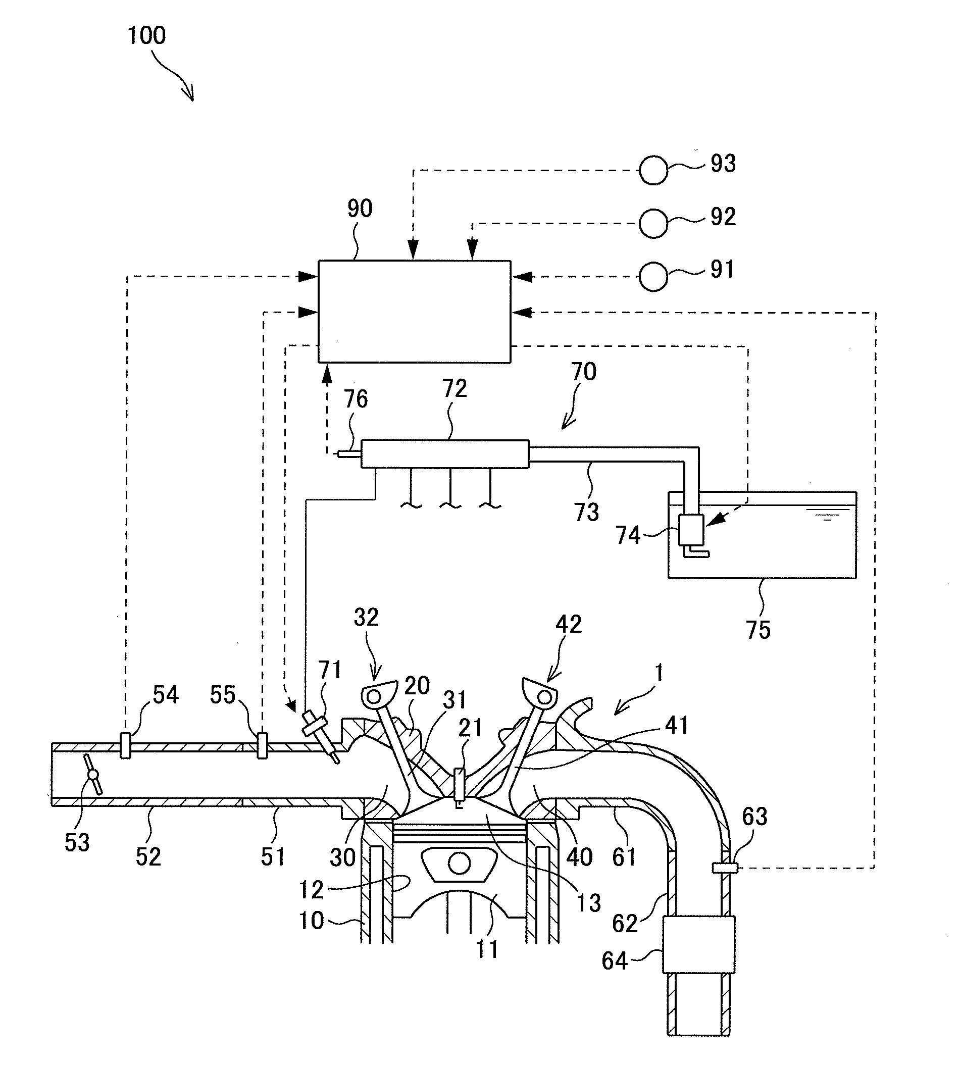
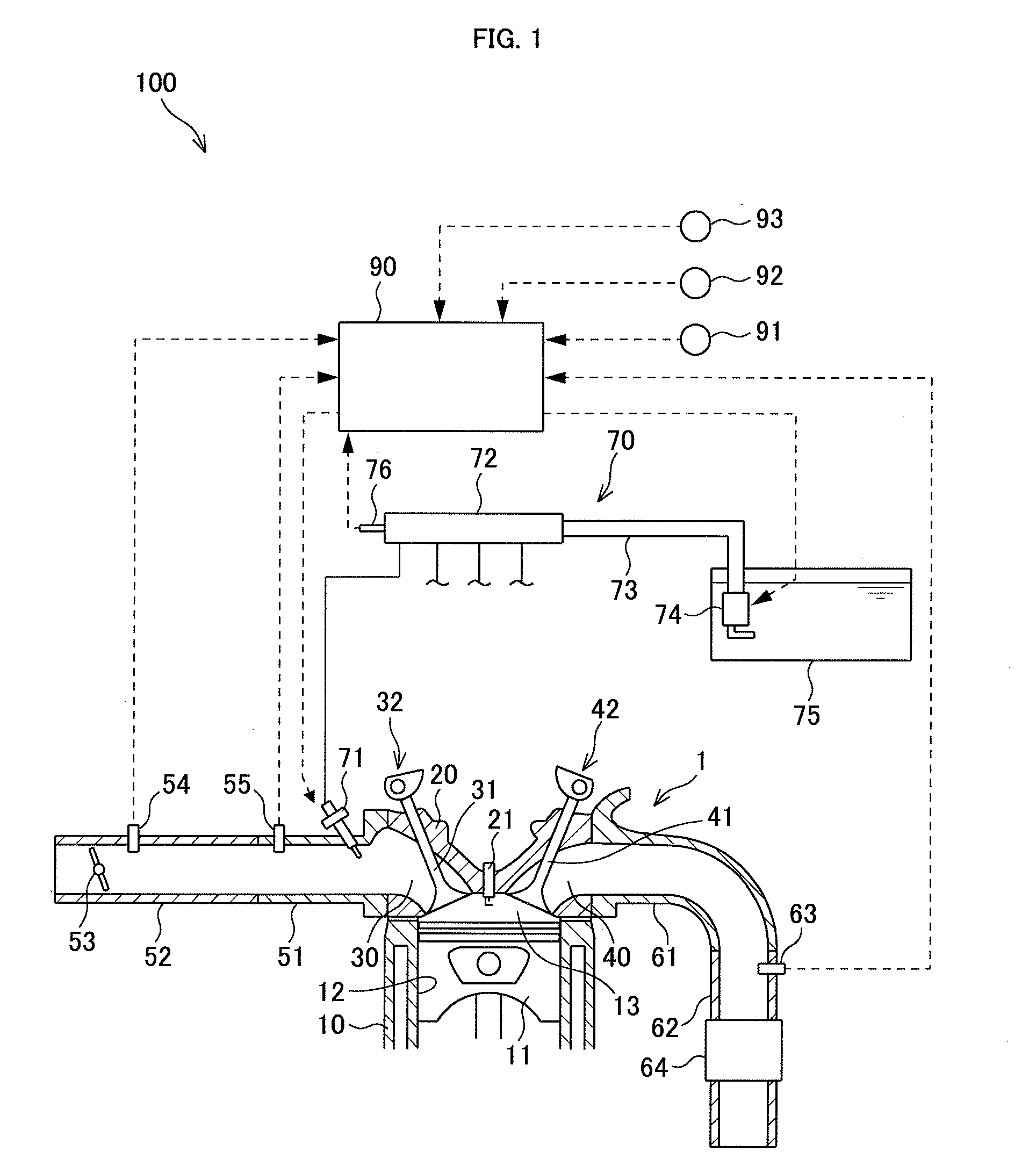
[0017]Hereinafter, a fuel injection control device 100 of an engine 1 according to an embodiment of the present invention will be explained with reference to FIG. 1 to FIG. 10.

[0018]As illustrated in FIG. 1, the fuel injection control device 100 is provided with the engine 1 and a controller 90 for controlling the engine 1.

[0019]The engine 1 is, for example, a serial 4-cylinder internal combustion engine that is mounted on a vehicle. The engine 1 is provided with a cylinder block 10 and a cylinder head 20 that is fixed to the upper portion of the cylinder block 10.

[0020]A cylinder 12 that receives a piston 11 in a slidable manner is formed in the cylinder block 10. The crown surface of the piston 11, the wall surface of the cylinder 12, and the bottom surface of the cylinder head 20 form a combustion chamber 13. When an air-fuel mixture is burned in the combustion chamber 13, the piston 11 receives a combustion pressure by the burning, and moves vertically along the cylinder 12.

[002...


PUM


Abstract

A fuel injection control device of an engine is disclosed, that is provided with a fuel injection valve configured to inject a fuel according to a target pulse width into an intake passage, an intake flow rate detection unit arranged to detect a flow rate of an intake air supplied to the engine, an intake pressure detection unit arranged to detect an intake pressure in the intake passage, a fuel pressure detection unit arranged to detect a pressure of a fuel supplied to the fuel injection valve, and a pressure control unit configured to control the fuel pressure according to an engine operation state. The device is further provided with a request pulse width calculation unit configured to calculate a request pulse width on the basis of an intake flow rate detected by the intake flow rate detection unit, a fuel pressure detected by the fuel pressure detection unit, and a differential pressure between the fuel pressure and an intake pressure detected by the intake pressure detection unit, a post-correction request pulse width calculation unit configured to calculate a post-correction request pulse width through correcting the request pulse width according to the differential pressure, when injecting a fuel of which flow rate is lower than a predetermined flow rate; and a target pulse width setting unit configured to set the target pulse width on the basis of the post-correction request pulse width.

Description

TECHNICAL FIELD[0001]The present invention relates to a fuel injection control device of an engine and a fuel injection control method of the engine.BACKGROUND ART[0002]JP1996-100695A discloses a fuel injection control device of an engine for controlling operation of a fuel injection valve that makes fuel injection into an intake passage. In consideration of an influence of an intake pressure in the intake passage exerted on a fuel injection amount of the fuel injection valve, this fuel injection control device calculates an effective injection time and an ineffective injection time based on a differential pressure between a fuel pressure and the intake pressure, and sets an injection time of the fuel injection valve from the effective injection time and the ineffective injection time.SUMMARY OF INVENTION[0003]Incidentally, the fuel injection valve that is mounted on the engine is controlled to open according to a target pulse width that defines a valve-opening time, and basically, ...

Claims


Application Information

Patent Timeline
Patent Type & Authority Applications(United States)
IPC IPC(8): F02D41/40F02D41/18
CPCF02D41/182F02D41/405F02D41/34F02D2041/001F02D2200/0406F02D2200/0602F02D2200/703F02D2250/31Y02T10/40
Inventor TERAUCHI, KAZUMICHIYOKOYA, SHIGEHIROAMANO, AKIOKATAYAMA, TAKATSUGU
Owner NISSAN MOTOR CO LTD
Why Eureka
Try Eureka