
Coil device

a coil device and coil technology, applied in the direction of transformer/inductance details, fixed inductances, inductances, etc., can solve the problems of reduced mounting strength between the terminal electrode and the circuit board, insufficient connection of insufficient connection of the parts and the terminal electrodes, so as to reduce thermal impact, reduce heat dissipation, and prevent breakage and cracks

Active Publication Date: 2016-07-28
TDK CORPARATION
View PDF14 Cites 20 Cited by
  • Summary
  • Abstract
  • Description
  • Claims
  • Application Information

AI Technical Summary

Benefits of technology

The present invention aims to provide a coil device that can connect wires securely and with minimal damage to the magnetic core. It also seeks to prevent dislocation while mounting the device.

Problems solved by technology

Thus, the coil device has a problem that the lead parts of the wire for winding and the terminal electrodes are prone to be connected insufficiently due to heat at the time of soldering for mounting the terminal electrodes on a circuit board, for example.
In particular, the lead parts and the terminal electrodes are prone to be connected insufficiently when the lead parts and the terminal electrodes are connected close to a mounting surface for compactness of the device.
Also, a problem that strength between the terminal electrode and the circuit board for mounting is decreased is caused.
When the lead part of the wire for winding and the terminal electrode are connected by laser welding, a magnetic core may be damaged by a laser beam and its reflection during laser welding.
It is conceivable that the magnetic core is damaged by breakage and crack due to thermal impact.
Then, the protruding portions may contact a device, such as a mounter, during transportation to a mounting machine, and its impact or stress may cause disconnection and break the core.
When a winding terminal without purpose for laser welding of a lead end is arranged near a magnetic core for compactness of the device and welded by laser as it is, the magnetic core may be also damaged by laser beam and its reflection during laser welding.

Method used


Image

  • Coil device
  • Coil device
  • Coil device

Examples


Embodiment Construction

[0063]Hereinafter, the present invention will be explained based on an embodiment shown in the figures.

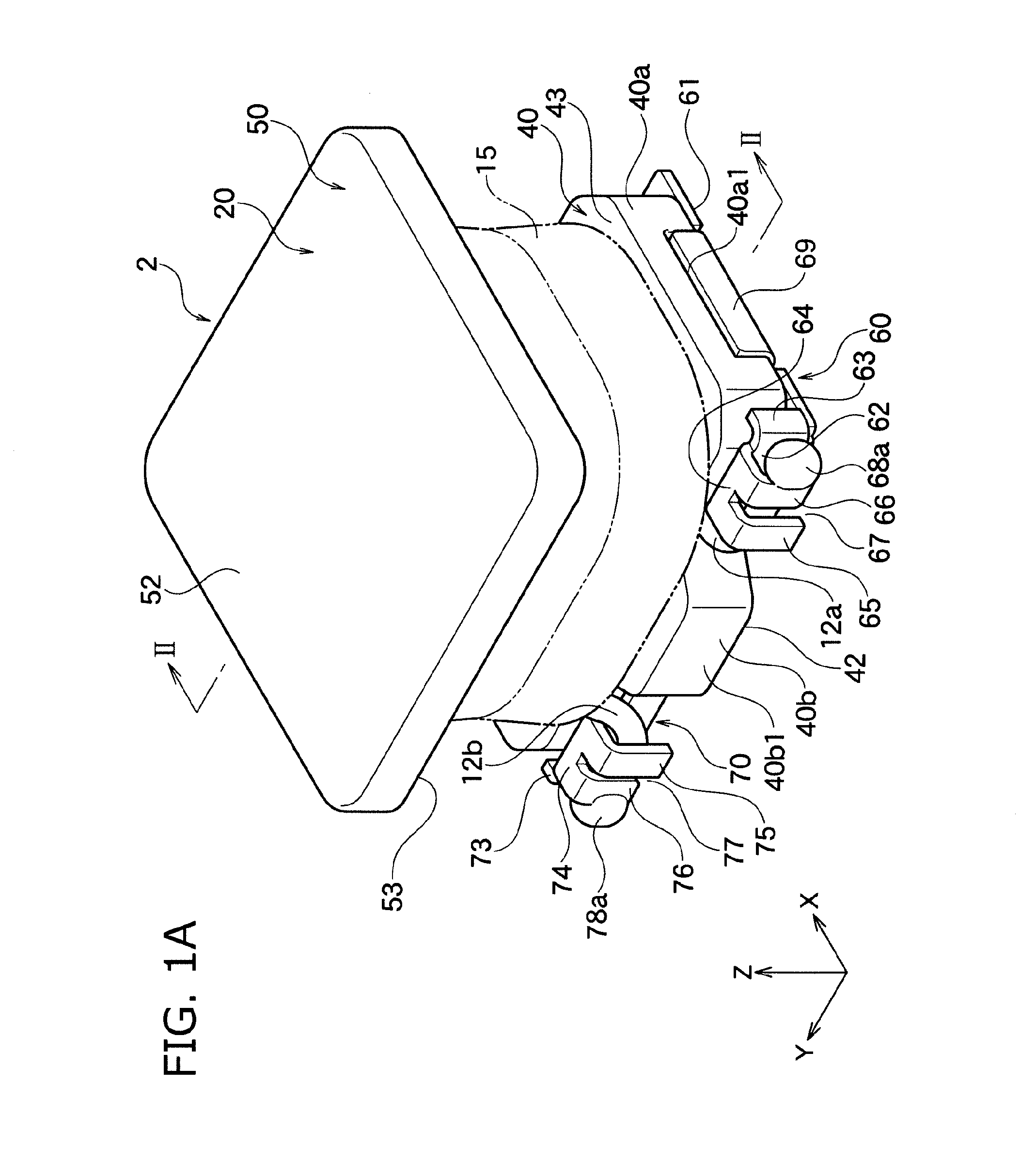
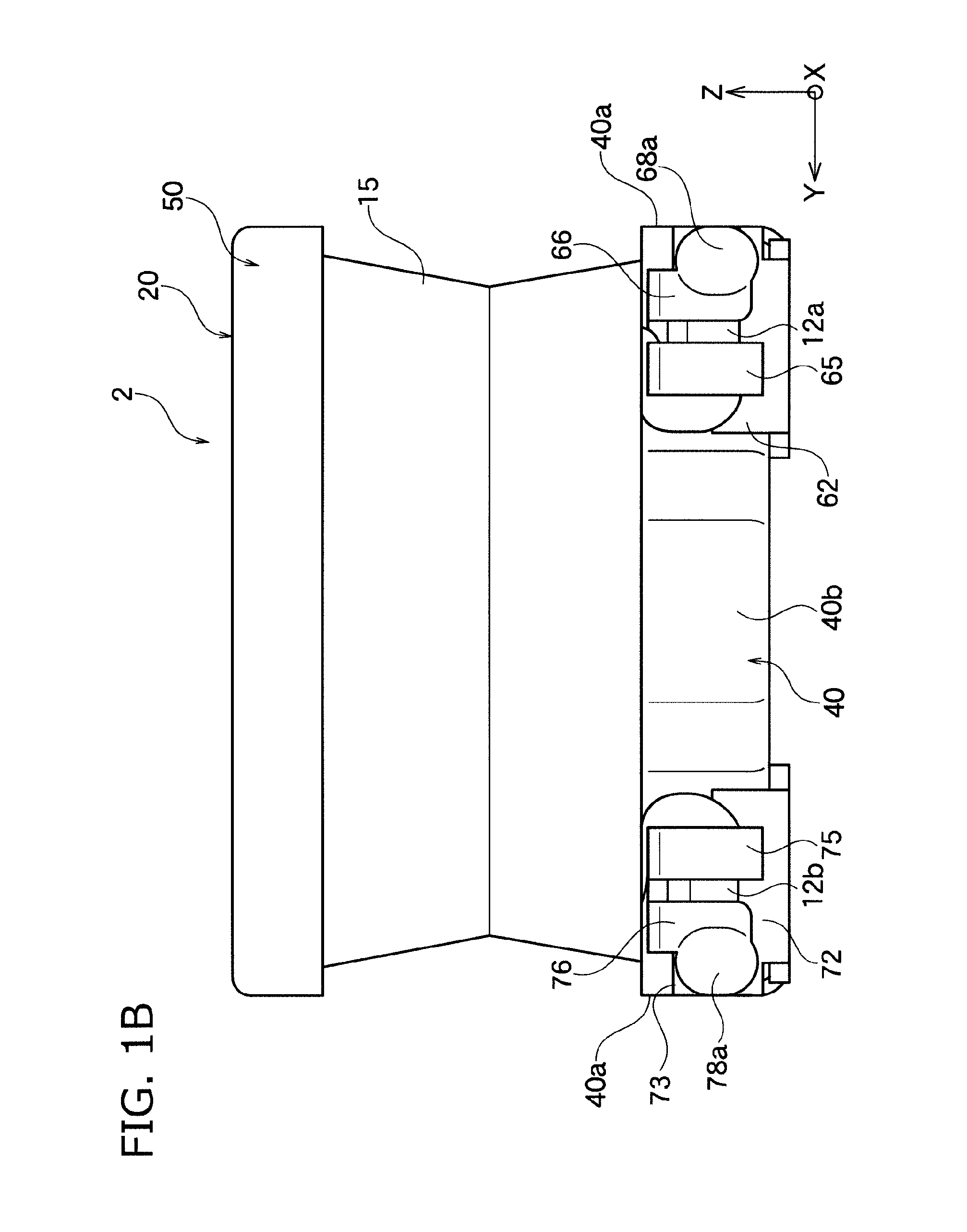
[0064]A coil device 2 according to one embodiment of the present invention shown in FIG. 1A to FIG. 1F is used as a choke coil or a noise filter, for example. In particular, the coil device 2 is preferably used for vehicles.

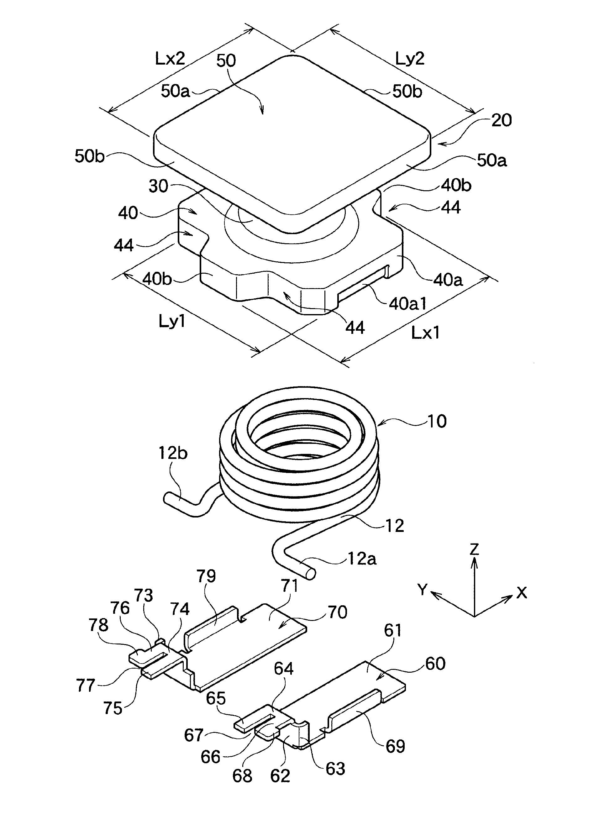
[0065]As shown in FIG. 2, the coil device 2 has a drum core 20 as a magnetic core. The drum core 20 is made of any magnetic material, such as soft magnetic material of metal or ferrite. The drum core 20 has a winding core 30 wound by a wire 12 of a coil part 10 along a winding axis direction of the core 20.

[0066]Preferably, an exterior resin 15 surrounds the winding core 30 wound by the wire 12. In this configuration, the coil part 10 can be effectively protected, and a short circuit failure can be prevented. Also, the exterior resin 15 is preferably made of a resin containing a magnetic body. In this configuration, the exterior resin 15 containing a magnetic bo...


PUM

PropertyMeasurementUnit
diameteraaaaaaaaaa
thicknessaaaaaaaaaa
outer diameteraaaaaaaaaa

Abstract

A coil device includes a magnetic core and terminal electrodes. The terminal electrodes include attachment pieces, wire connection rising pieces, connection pieces, and fillet forming pieces. The wire connection rising pieces are integrally risen from one ends in a longitudinal direction of the attachment pieces along a side surface in the X-axis direction of a flange. The connection pieces are integrally formed with upper end sides of the wire connection rising pieces and have welded balls connected to lead parts of a wire by laser welding. The fillet forming pieces are integrally risen from one ends in a lateral direction crossing the longitudinal direction of the attachment pieces along a side surface in the Y-axis direction of the flange. Laser shielding members are arranged between the welded balls and the flange of a magnetic core.

Description

BACKGROUND OF THE INVENTION[0001]1. Field of the Invention[0002]The present invention relates to a coil device, and specifically relates to a coil device capable of performing wire connection in a firm and secure manner.[0003]2. Description of the Related Art[0004]A drum core and a terminal shape as shown in a publication (WO2009 / 034860), for example, are well known for thinning. In the coil device shown in the publication, however, lead parts of a wire for winding are soldered with terminal electrodes.[0005]Thus, the coil device has a problem that the lead parts of the wire for winding and the terminal electrodes are prone to be connected insufficiently due to heat at the time of soldering for mounting the terminal electrodes on a circuit board, for example. In particular, the lead parts and the terminal electrodes are prone to be connected insufficiently when the lead parts and the terminal electrodes are connected close to a mounting surface for compactness of the device.[0006]It...

Claims


Application Information

Patent Timeline
Patent Type & Authority Applications(United States)
IPC IPC(8): H01F27/29H01F27/28
CPCH01F27/2823H01F27/29H01F17/045H01F27/306
Inventor IWATA, HIROYUKITAKAGI, NOBUOABE, HIROYUKISHIMURA, KOJI
Owner TDK CORPARATION
Learn More