Microstrip patch antenna array

Inactive Publication Date: 2016-07-28
TE CONNECTIVITY CORP
View PDF3 Cites 8 Cited by
  • Summary
  • Abstract
  • Description
  • Claims
  • Application Information

AI Technical Summary

Problems solved by technology

This approach causes the microstrip patch antennas to produce surface waves in the substrate, reducing the radiated power and degrading the radiation pattern performance of the array.
These individual microstrip patch antennas can be secured to a surface using adhesive; however, such arrays are not suitable for all applications.
Fo

Method used


Image

  • Microstrip patch antenna array
  • Microstrip patch antenna array
  • Microstrip patch antenna array

Examples


Embodiment Construction

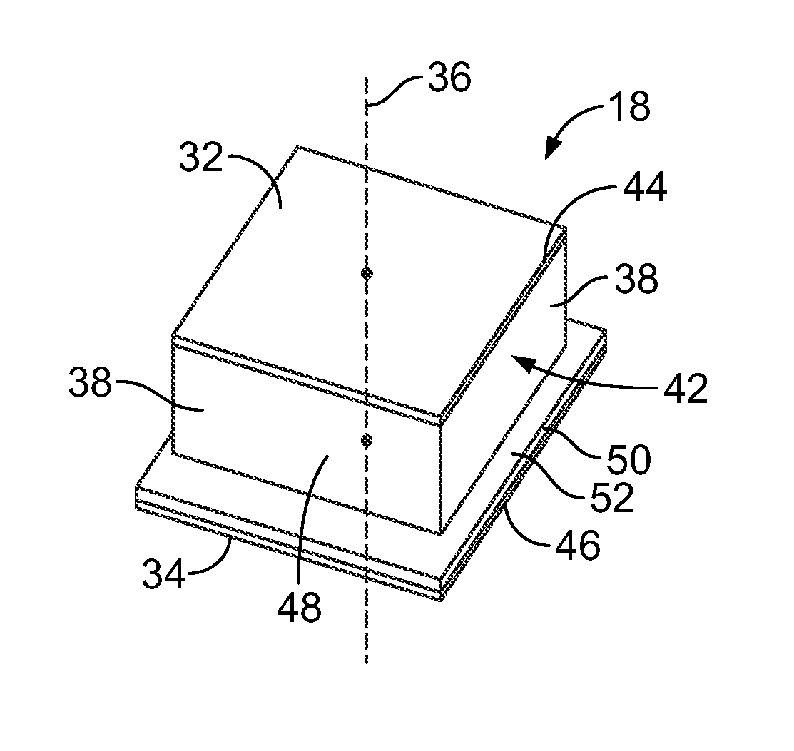
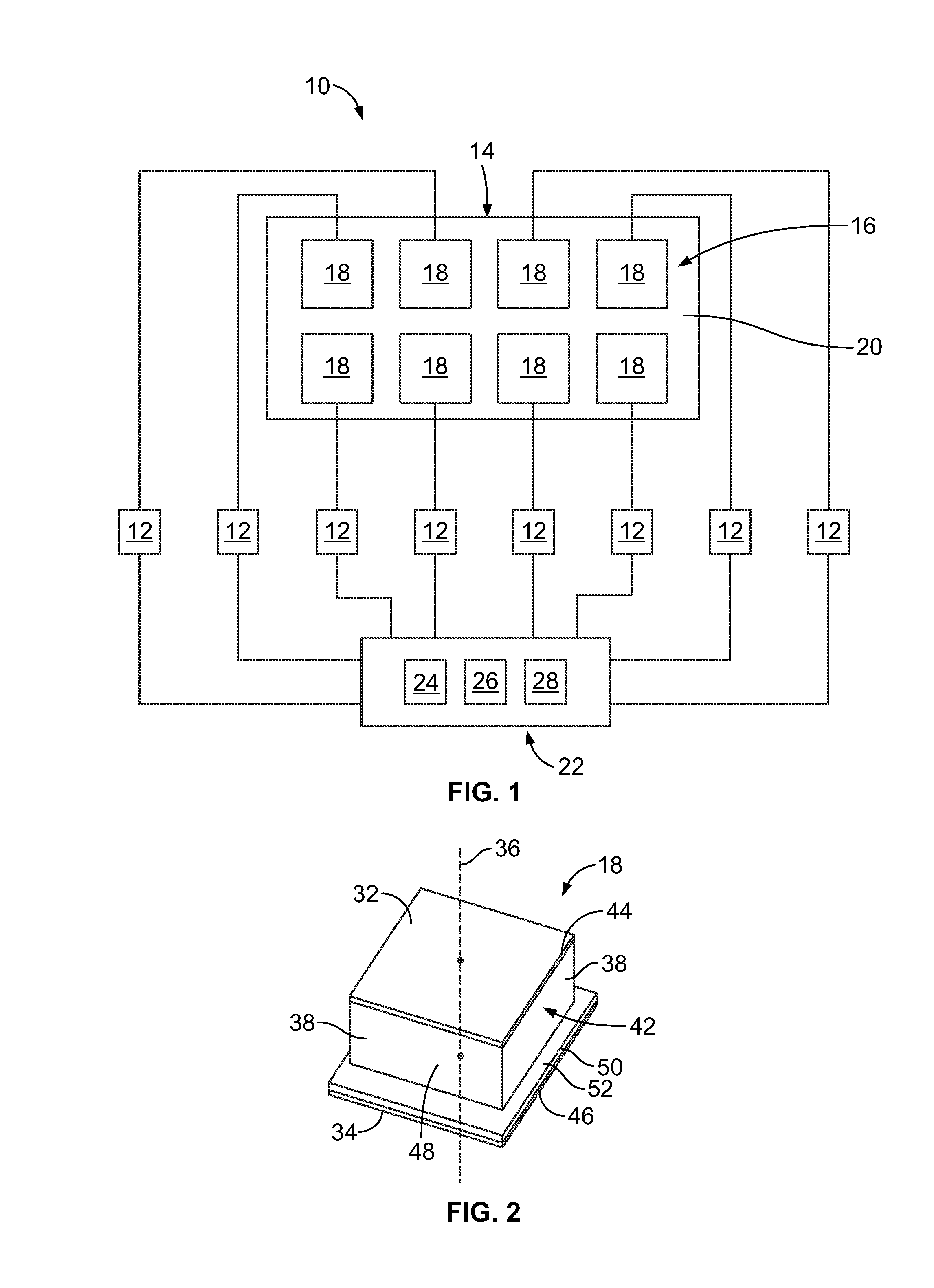
[0016]FIG. 1 is a schematic diagram of an exemplary embodiment of an antenna system 10. The antenna system 10 includes a plurality of feed networks 12 and an antenna assembly 14. The antenna assembly 14 includes a patch antenna array 16 of patch antenna elements 18, such as microstrip patch antenna elements 18. The patch antenna array 16 may include any number of patch antenna elements 18, the antenna assembly 14 may include any number of the patch antenna arrays 16, and the antenna assembly 14 may include any number of patch antenna elements 18 overall. The patch antenna elements 18 may be arranged within the patch antenna array 16 in any pattern, including in the grid pattern shown in FIG. 1 of multiple columns and multiple rows of patch antenna elements 18.

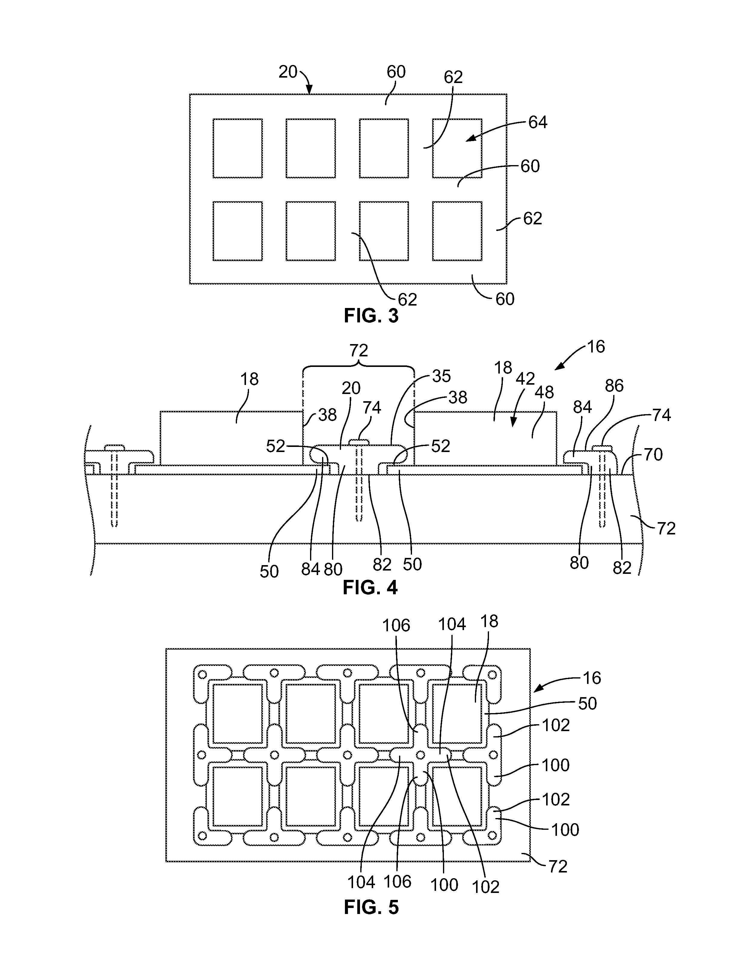
[0017]In an exemplary embodiment, the patch antenna elements 18 are discrete and separate components that are arranged together to form the patch antenna array 16. The antenna assembly 14 includes one or more element frames 20 ...


PUM


Abstract

A patch antenna array includes a plurality of patch antenna elements spaced apart from each other and arranged as an array. Each patch antenna element has a substrate, a radiating patch associated with the substrate and a ground plane associated with the substrate. The patch antenna elements are discrete and separate from each other. At least one element frame holds the discrete antenna elements in the array. Each element frame captures and positions at least two patch antenna elements relative to each other.

Description

BACKGROUND OF THE INVENTION[0001]The subject matter disclosed herein relates generally to microstrip patch antenna arrays.[0002]Microstrip patch antennas are commonly used with electronic receivers for communication systems, such as global navigation satellite systems (GNSSs). A microstrip patch antenna is a type of antenna that typically includes a flat sheet, or patch, of metal that is mounted over a ground plane. Known patch antennas are not without disadvantages. For example, patch antennas arranged in arrays are typically printed on a single substrate. This approach causes the microstrip patch antennas to produce surface waves in the substrate, reducing the radiated power and degrading the radiation pattern performance of the array. Some known patch antenna arrays overcome surface wave excitation problems by providing arrays of individual microstrip patch antennas, each with a separate substrate. These individual microstrip patch antennas can be secured to a surface using adhes...

Claims


Application Information

Patent Timeline
IPC IPC(8): H01Q21/06H01Q9/04
CPCH01Q21/065H01Q9/045H01Q9/0407H01Q1/1207H01Q1/246H01Q21/08
Inventor FASENFEST, KATHLEENTALLY, PAUL CRAIGRATZLAFF, THOMAS DEAN
Owner TE CONNECTIVITY CORP
Why Eureka
Try Eureka