Charging station for mobile device with solar panel

Active Publication Date: 2016-07-28
ALTA DEVICES INC
View PDF0 Cites 26 Cited by
  • Summary
  • Abstract
  • Description
  • Claims
  • Application Information

AI Technical Summary

Benefits of technology

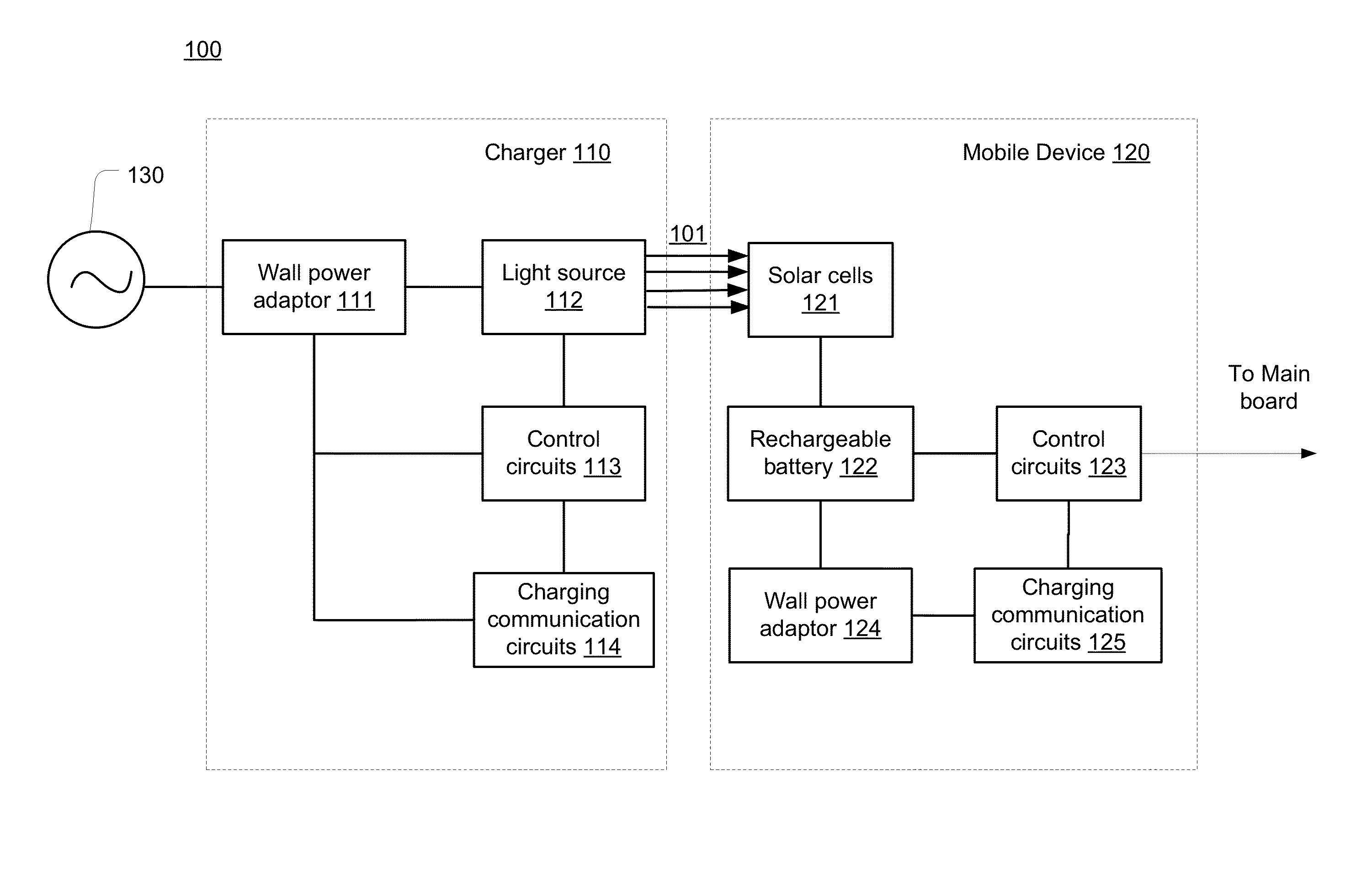
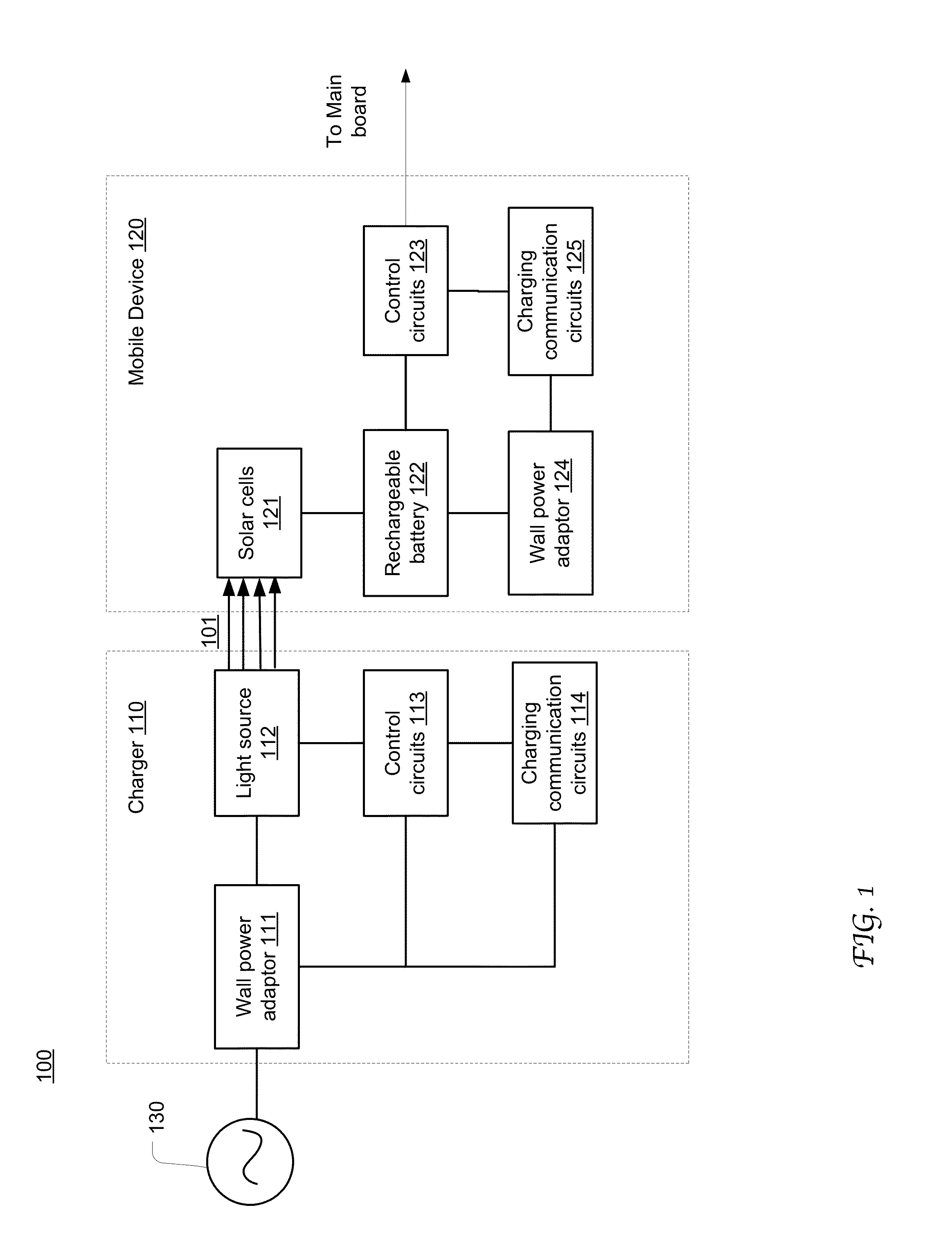
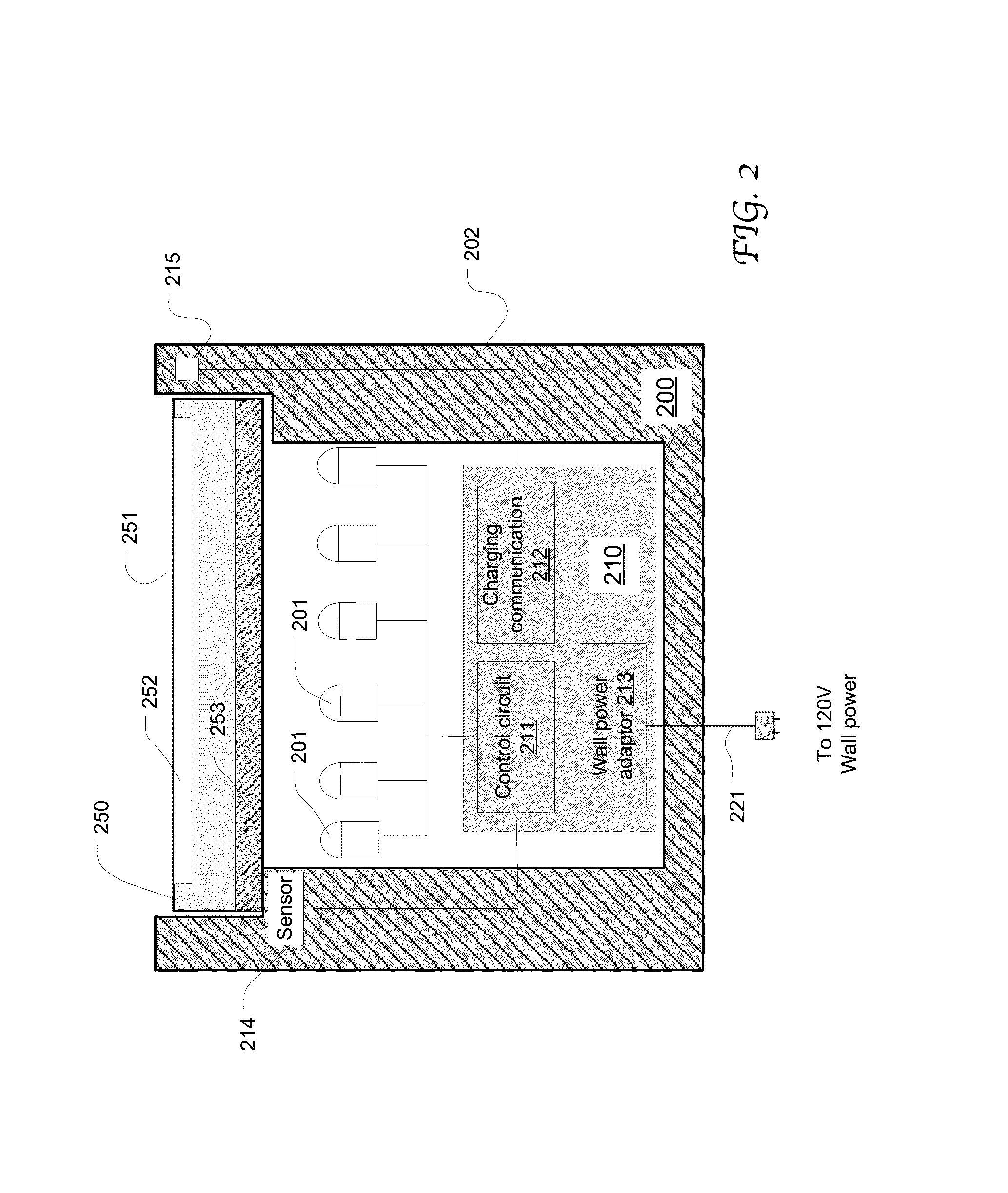
[0007]Embodiments of the present disclosure provide a charging device configured to convert wall power to light energy which can be absorbed by the solar cells (or photovoltaic cells) installed on a mobile device and then converted to electricity for storage in the rechargeable battery of the mobile device. The charging device includes a light source configured to emit light beams with a spectrum tuned to the spectral response of the solar cells, thereby achieving a photovoltaic efficiency exceeding that of solar charging by ambient light. The intensity of the light source can also be increased to increase the power density of the light received by the photovoltaic cells, relative to ambient light. The housing of the charging device is designed to accommodate a mobile device placed therein with the solar cells facing the light source. The charging device includes a proximity sensor for detecting the presence of a mobile device within the hosing of the charging device and sending corresponding signals to trigger the activation of the light source. The charging device is equipped with log

Problems solved by technology

Currently, mobile devices with solar cells have to preserve the capabilities of wired charging for rapid charging, especially when the ambient light intensity is insufficient for so

Method used


Image

  • Charging station for mobile device with solar panel
  • Charging station for mobile device with solar panel
  • Charging station for mobile device with solar panel

Examples


Example

[0015]Reference will now be made in detail to the preferred embodiments of the present invention, examples of which are illustrated in the accompanying drawings. While the invention will be described in conjunction with the preferred embodiments, it will be understood that they are not intended to limit the invention to these embodiments. On the contrary, the invention is intended to cover alternatives, modifications and equivalents, which may be included within the spirit and scope of the invention as defined by the appended claims. Furthermore, in the following detailed description of embodiments of the present invention, numerous specific details are set forth in order to provide a thorough understanding of the present invention. However, it will be recognized by one of ordinary skill in the art that the present invention may be practiced without these specific details. In other instances, well-known methods, procedures, components, and circuits have not been described in detail ...


PUM


Abstract

A charging device configured to charge a mobile device through the solar cells integrated on the mobile device. The charging device converts wall power to light energy which can be absorbed by the solar cells and then converted to electricity for storage in the rechargeable battery of the mobile device. The charging device includes a light source configured to emit a light beam having a spectrum tuned to the spectral response of the solar cells. The charging device includes a proximity sensor for detecting the presence of a mobile device within the charging device housing and responsively signaling the activation of the light source. The charging device includes logic for wirelessly communicating with the mobile device as well as controlling the charging process in various stages and aspects. The light source may be LEDs that also serve to transmit light communication signals to the mobile device.

Description

CROSSREFERENCE[0001]This application claims priority and benefit to the U.S. Provisional Patent Application No. 62 / 106,636, filed on Jan. 22, 2015, titled “LIGHT CHARGING DOCK FOR CHARGING MOBILE DEVICE WITH SOLAR CELL,” the entire content of which is herein incorporated by reference.TECHNICAL FIELD[0002]The present disclosure relates generally to the field of mobile devices, and, more specifically, to the field of charging accessories for mobile devices.BACKGROUND OF THE INVENTION[0003]The density and speed of integrated circuit elements have steadily and exponentially increased for several decades, allowing for ever faster processing speeds, greater data handling capabilities, increasing storage capacity, and smaller physical dimensions of mobile electronic devices, such as smart phones, tablets, media players, global positioning system (GPS) and personal digital assistants (PDAs). With the ever increased amount of information available on computer networks as well as mobile devic...

Claims


Application Information

Patent Timeline
IPC IPC(8): H02J7/35H02J7/00
CPCH02J7/355H02J7/0044H02J7/0036H02J7/025H02J50/30H02J7/35H02J50/90
Inventor HE, GANGKAYES, BRENDANFRANCE, CHRISTOPHER
Owner ALTA DEVICES INC
Why Eureka
Try Eureka