Voice coil motor and direct-acting servo valve using the voice coil motor

a voice coil motor and voice coil technology, which is applied in the direction of valves, mechanical devices, propulsion systems, etc., can solve the problems of increased cost, deteriorated responsiveness, and difficulty in manufacturing ring-shaped magnets, and achieve high endurance and high magnetic efficiency.

Active Publication Date: 2016-07-28
SANTEST
View PDF6 Cites 4 Cited by
  • Summary
  • Abstract
  • Description
  • Claims
  • Application Information

AI Technical Summary

Benefits of technology

[0033]As described above, according to the present invention, an axially magnetized magnet of an inner magnet array is formed of an monolithic ring-shaped magnet, a radially magnetized magnet of the inner magnet array is formed of a plurality of split magnets which are divided in a circumferential direction, and a fixing means is arranged to fix the radially magnetized magnet and the axially magnetized magnet of the inner magnet array in an axially clamped manner. In this way, the split magnets can be prevented from popping outwardly even though the split magnets placed adjacently in the circumferential direction repel each other. Therefore, a voice coil motor having a high magnetic efficiency and a high endurance can be created.

Problems solved by technology

However, because total mass of these voice coil motors is also doubled, this case may result in a deteriorated responsiveness in some degree.
Further, because two amplifiers are necessary for driving the voice coil motors, a problem of increased cost in addition to the problem of increased heat generation caused by the voice coil motors may occur.
However, it is difficult to manufacture the ring-shaped magnets 101 and 111 which are radially magnetized in a favorable manner.
This is because it is difficult to magnetize a ring-shaped magnet such that it has effective and high magnetic flux density in its radial direction due to the difference between the area of the inner peripheral surface and that of the outer peripheral surface of the ring-shaped magnet.
Particularly, in case there is a large difference between the inner and outer diameters, it is more difficult to radially magnetize the ring-shaped magnet effectively.
Thus, the adhesive tends to be broken due to disturbances such as changes in ambient temperature or vibration, so that the split magnets may possibly pop outwardly in the radial direction.
Consequently, the radially magnetized magnets may not be able to work anymore.
However, the split magnets cannot be prevented from popping outwardly because their outer peripheral surfaces are not supported in surrounding manner.
If a split magnet pops outwardly, it may interfere with the coil, resulting in a failure in the operation of the voice coil motor.

Method used


Image

  • Voice coil motor and direct-acting servo valve using the voice coil motor
  • Voice coil motor and direct-acting servo valve using the voice coil motor
  • Voice coil motor and direct-acting servo valve using the voice coil motor

Examples


first embodiment

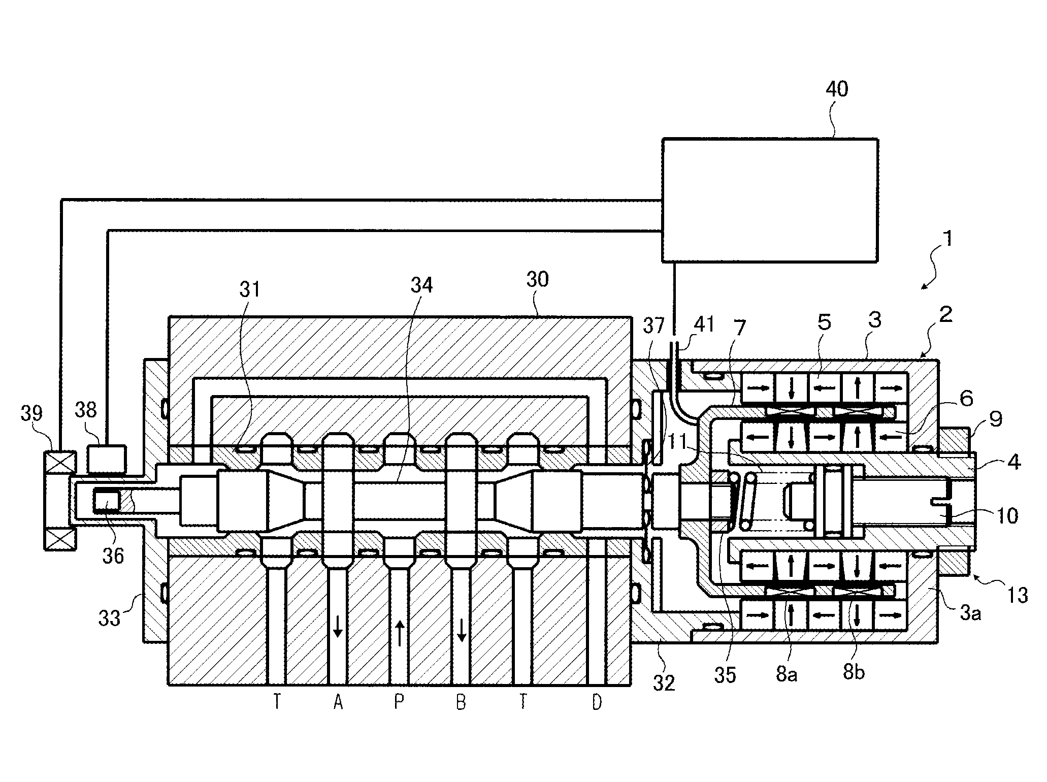
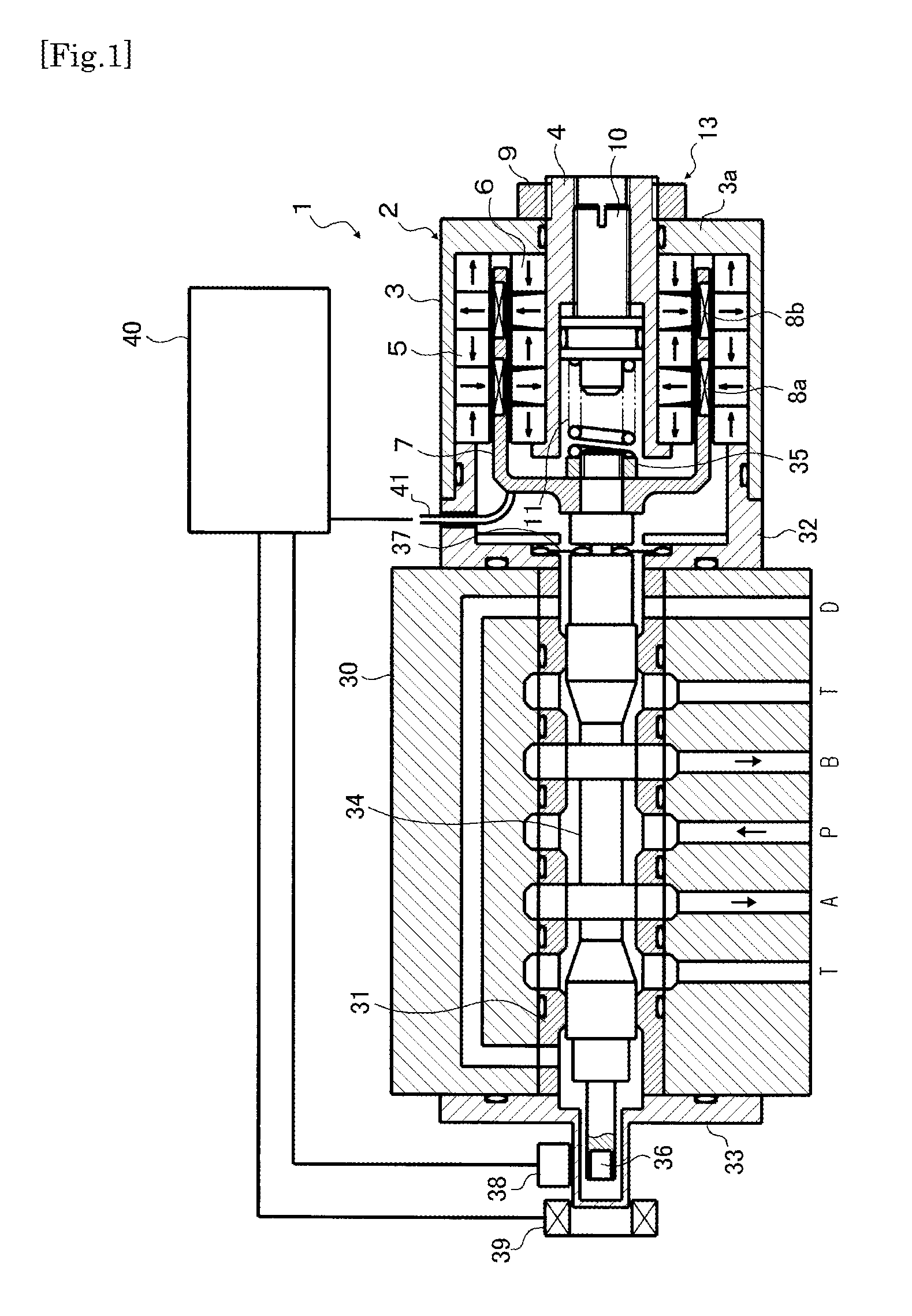
[0045]FIG. 1 shows a direct-acting servo valve 1 using a voice coil motor 2 according to a first embodiment of the present invention. With respect to the voice coil motor 2, detailed description will be given referring to FIG. 2, and only brief description of the functions of the representative components thereof will be given regarding FIG. 1. A sleeve 31 is inserted into the middle of valve body 30 of the servo valve 1, and the sleeve 31 is fixed by side plates 32 and 33 provided on both axial ends of the valve body 30.

[0046]A spool 34 is inserted in a center of the sleeve 31 in axially movable manner. An axial end portion of the spool 34 is fixed to a coil bobbin 7 of a voice coil motor 2 (as described below) by a nut 35, and the other axial end portion of the spool 34 is provided with a magnet 36 attached thereto. FIG. 1 shows the spool 34 in a state in which it is neutrally positioned with respect to the sleeve 31. The pressurized fluid (e.g. hydraulic oil) supplied in an inlet...

second embodiment

The Second Embodiment

[0064]FIG. 5 shows a second embodiment of a voice coil motor according to the present invention. The same reference signs are used for denoting the same parts or the corresponding parts of the first embodiment in order to omit a repeated explanation.

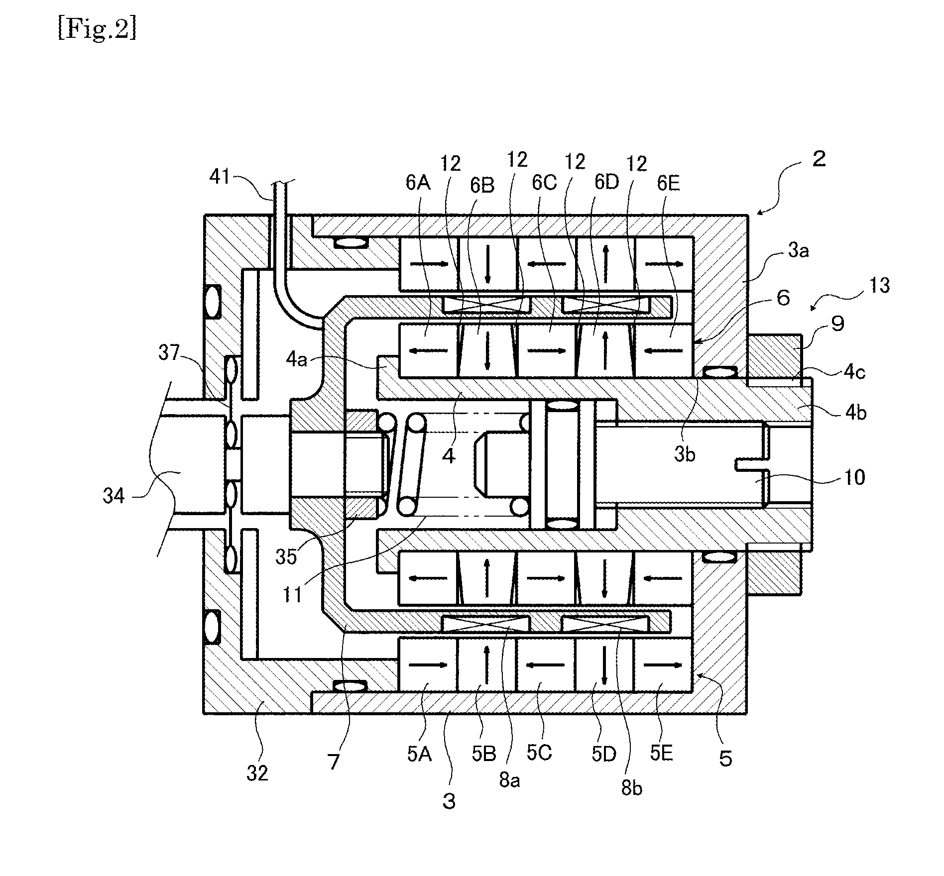
[0065]In this embodiment, each of the radially magnetized magnets (split magnets) 6B and 6D of the inner magnet array 6 has a trapezoidal shape in which the upper base is shorter than the bottom base in its cross section, in the same way as the first embodiment, whereas each of the ring-shaped axially magnetized magnets 6A, 6C and 6E has a trapezoidal shape in which the upper base is longer than the bottom base in its cross section. Namely, the split magnets 6B and 6D have the inclined surfaces 60 and 61 at both sides in the axial direction, whereas the axially magnetized magnets 6A, 6C and 6E have tapered surfaces 62 at their axial sides opposing the inclined surfaces 60 and 61. In this case also, in the same way as...

third embodiment

The Third Embodiment

[0066]FIGS. 6 and 7 show a third embodiment of a voice coil motor according to the present invention. The same reference signs are used for denoting the same parts or the corresponding parts of the first embodiment in order to omit a repeated explanation. In this embodiment, after a plurality of the split magnets 6B and 6D radially magnetized are assembled into a ring-shape, the outer periphery thereof is surrounded by a thin non-magnetic tube 14. In this case, the cross-sections of the radially magnetized magnets (split magnets) 6B and 6D as well as the axially magnetized magnets 6A, 6C and 6E need not to be trapezoids, namely, they may be typical rectangular.

[0067]By this configuration, the split magnets composing the radially magnetized magnets 6B and 6D of the inner magnet array 6 can be prevented from popping outwardly effectively. Because the tube 14 is made of a non-magnetic material, the magnetic field generated by the radially magnetized magnets 6B and 6...


PUM


Abstract

A voice coil motor 2 using a Dual Halbach Magnet Array has an outer magnet array 5 and an inner magnet array 6, wherein the inner magnet array 6 comprises axially magnetized magnets 6A, 6C and 6E and radially magnetized magnets 6B and 6D. Each of the axially magnetized magnets 6A, 6C and 6E of an inner magnet array 6 is formed of a monolithic magnet having ring-shape, whereas each of the radially magnetized magnets 6B and 6D of the inner magnet array 6 is formed of a plurality of split magnets divided in a circumferential direction. A fixing means 13 is provided to fix the radially magnetized magnets 6B and 6D and the axially magnetized magnets 6A, 6C and 6E of the inner magnet array 6 in an axially clamped manner.

Description

FIELD OF THE INVENTION[0001]The present invention relates to a voice coil motor and a direct-acting servo valve using the voice coil motor.BACKGROUND OF THE INVENTION[0002]A voice coil motor, as is well known, comprises cylindrical magnets, an outer yoke and an inner yoke. The voice coil motor also comprises a cylindrical coil that is arranged in an annular space in which magnetic field is intensively generated, such that the coil is driven in an axial direction when current is supplied to the coil. Direct-acting (linear driving) servo valves using such voice coil motors are known to public. The direct-acting servo valve drives a spool placed in a valve body in an axial direction by means of the voice coil motor, and switches the communication between ports provided on the valve body by opening and closing the ports. As a result, the flow rate of fluid flowing through the ports is regulated, and velocity, position or forces of a loading device such as a hydraulic cylinder or a fluid...

Claims


Application Information

Patent Timeline
Patent Type & Authority Applications(United States)
IPC IPC(8): H02K41/035F16K31/04F16K11/065
CPCH02K41/0356F16K31/04F16K11/065H02K33/18H02K7/14F16K31/082F16K11/07F16K31/0679
Inventor KOZO, KYOIZUMI
Owner SANTEST
Why Eureka
Try Eureka