Adjustable drainage valve

a technology of drainage valve and adjustment valve, which is applied in the direction of valves, medical devices, other medical devices, etc., can solve the problems of not having a valve that allows treatment of all types of hydrocephalus, and achieve the effects of improving precision, ensuring maximum precision, and ensuring mechanical precision

Active Publication Date: 2016-08-04
SOPHYSA SA
View PDF2 Cites 23 Cited by
  • Summary
  • Abstract
  • Description
  • Claims
  • Application Information

AI Technical Summary

Benefits of technology

[0017]Furthermore, for the same angular rotation of the rotor, the length of camway traveled by the point of contact of the elastic return member increases with greater distance of the point of contact away from the axis X and becomes shorter as this point of contact nears the axis. The successive angular positions corresponding to points of contact away from the axis X are therefore separated from one another by a longer length of camway than those corresponding to points of contact near the axis X. They may therefore be defined with greater mechanical precision, giving better precision to the corresponding opening pressures. Unlike the existing configurations in which the cam has an exterior profile which, for a point of contact distant from the center of the rotor, afford maximum precision in the high opening pressures, the design in which the cam has an interior profile affords maximum precision at the low opening pressures. This design is therefore better suited to the physiological needs of the patients as it affords high precision in the low pressures, where a 10 mm H2O difference in pressure may have a significant effect on the clinical condition of the patient, as in certain cases of normal pressure hydrocephalus or low pressure hydrocephalus, and lower precision in the very high pressures, where a variation of a few tens of mm H2O has only a limited impact on the clinical condition of the patient. As will be seen in more detail later on in the description, the camway may thus advantageously be very extensive about the axis X of the rotor. The setting of the influence exerted by the elastic return member on the shutter, namely the setting of the opening pressure, may therefore be very precise and / or the range of opening pressures may be very broad.

Problems solved by technology

Because on the one hand of the limited amplitude of the ranges of opening pressures available, and on the other hand of the limitation on the number of opening pressures available with a given model, notably in the range of high opening pressures, there is, however, today no valve that allows treatment of all types of hydrocephalus.

Method used


Image

  • Adjustable drainage valve
  • Adjustable drainage valve
  • Adjustable drainage valve

Examples


Embodiment Construction

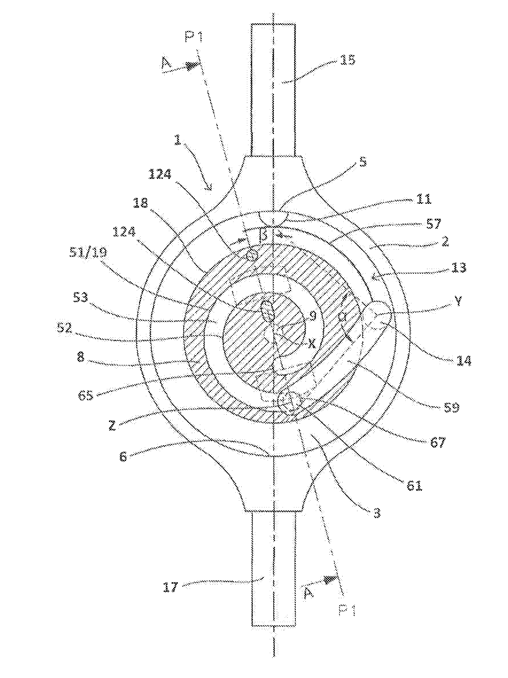
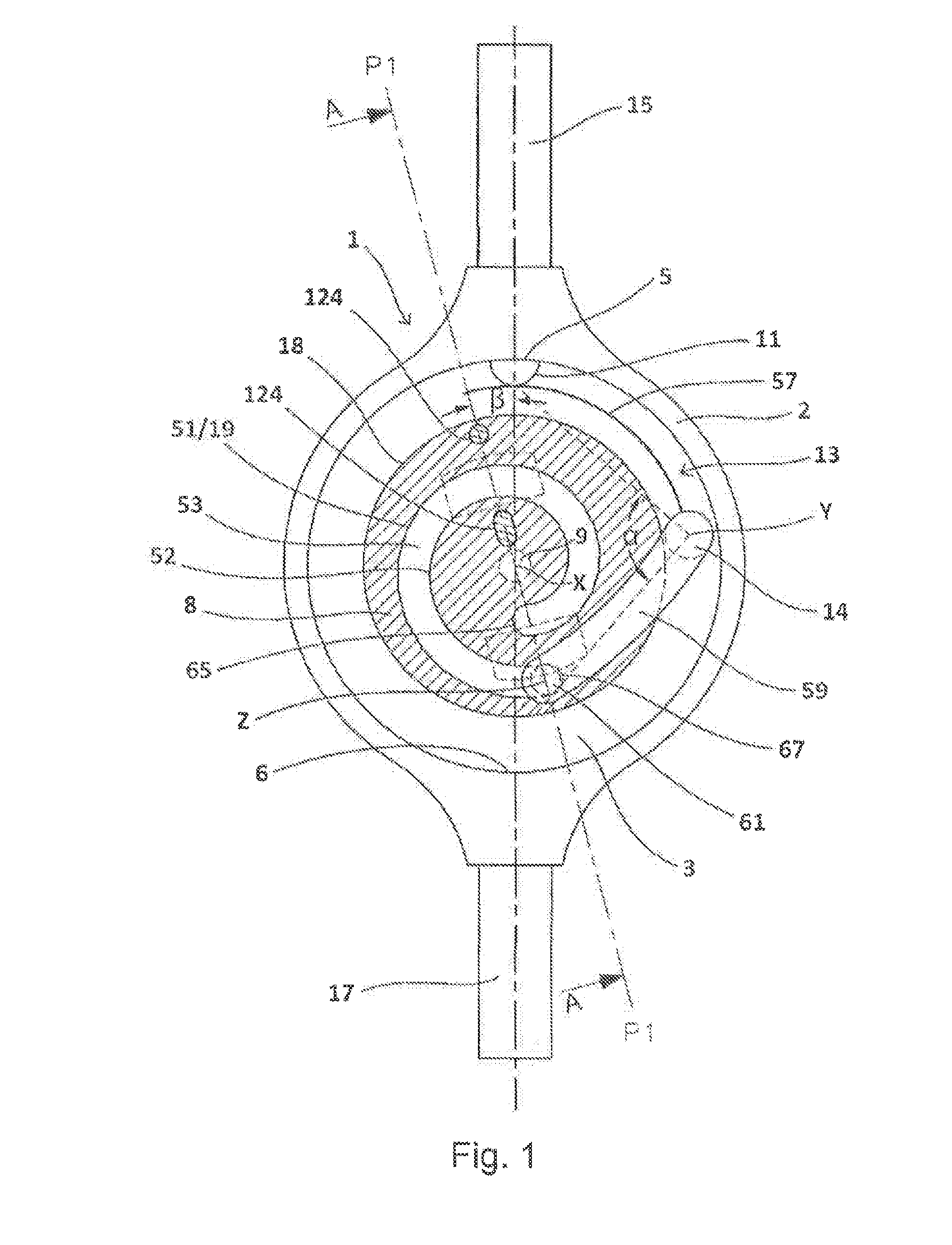
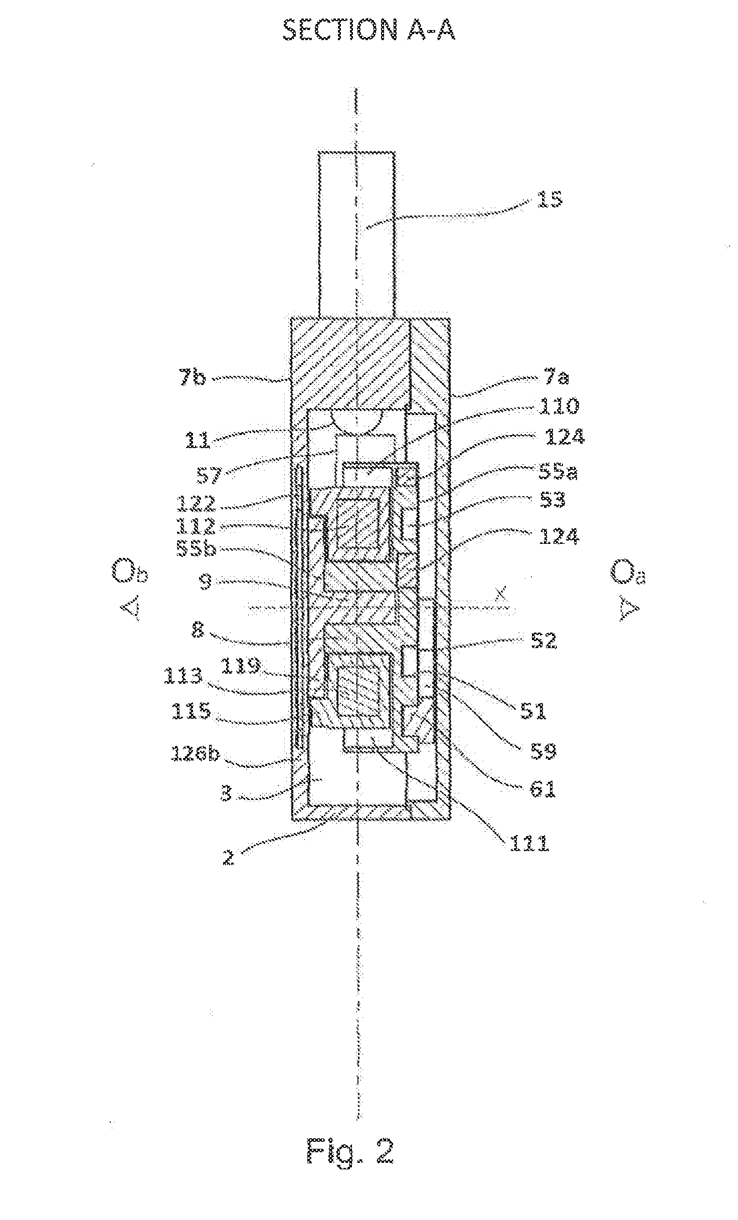
[0064]The figures depict drainage valves 1 according to the invention, each comprising a body 2 defining a chamber 3 into which inlet 5 and outlet 6 orifices open. The chamber 3 is preferably substantially symmetrical, in particular with respect to the axis connecting the inlet 5 and outlet 6 orifices. For preference, it is substantially cylindrical of axis X.

[0065]The body 2 comprises an internal 7a and an external 7b face which faces are intended, after the device has been implanted under the skin of a patient, to be oriented toward the inside and the outside of the body of the patient, respectively.

[0066]A rotor 8, mounted with the ability to rotate about a pivot 9 of axis X of the body, a shutter consisting of a ball 11 and an elastic return member 13 pressing elastically against the ball 11 to hold it against the inlet orifice 5, are housed in the chamber 3.

[0067]An inlet pipe 15 and an outlet pipe 17 are fixed to the body 2 and open respectively via the inlet 5 and outlet 6 or...


PUM


Abstract

A drainage valve intended to be implanted and to drain the cerebrospinal fluid, including: a body defining a chamber into which there open an inlet port and an outlet port, a stopper capable of at least partially, or indeed completely, closing off the inlet port, a resilient return member exerting a resilient push force on the stopper towards the inlet port in order to open or close the port, a rotor housed in the chamber, able to rotate about an X-axis pivot and including a cam track on which the resilient return member rests such that the force exerted by the resilient return member on the stopper is modified by the rotation of the rotor.

Description

TECHNICAL FIELD[0001]The subject of the present invention is a drainage valve intended for therapeutic applications, notably for the treatment of hydrocephalus which consists in shunting cerebrospinal fluid (CSF) contained in the ventricles of the cranial cavity toward a resorption site, for example the peritoneal cavity. The valve can be controlled from the outside in order, through the cutaneous tissues, to modify the passage or distribution of this fluid.PRIOR ART[0002]European patent EP 0 688 575 B1 discloses such a valve. It comprises a rotor to which a curved leaf spring is attached, the leaf spring pressing elastically against a ball in order to hold it against an inlet orifice of the valve so as to regulate the passage of fluid through this inlet orifice. The rotation of the rotor causes the point of contact of the ball on the leaf spring to slide, thereby altering the influence exerted by the leaf spring on the ball (corresponding to an opening pressure). The rotor may be l...

Claims


Application Information

Patent Timeline
Patent Type & Authority Applications(United States)
IPC IPC(8): A61M27/00A61M39/24
CPCA61M27/006A61M2205/3515A61M39/24A61M2205/0272A61M2039/2433A61M2039/2493A61M2039/242
Inventor NEGRE, PHILIPPE
Owner SOPHYSA SA
Why Eureka
Try Eureka