Fir tree mount

a tree mount and bundle technology, applied in the field of bundle retention devices, can solve the problems of insufficient retention and tightness against the support surface of known bundle retention devices, many known mounts do not provide a high ratio of mechanical advantage and high retention strength, and many known bundle retention devices may not provide adequate retention and tightness against the support surfa

Inactive Publication Date: 2016-08-04
HELLERMANNTYTON CORP
View PDF21 Cites 18 Cited by
  • Summary
  • Abstract
  • Description
  • Claims
  • Application Information

AI Technical Summary

Benefits of technology

[0009]The present invention provides an improved bundle retention and mounting device for securely retaining and supporting bundled items against a supporting surface. The device provides a mount with an aperture, which interacts with a flexible tie strap having serrations, for bundling elongate items. The tie may be integrally formed with the device. The aperture contains a wedging pawl, which provides ratcheting engagement of the serrations when the tie tail, followed by the strap, is inserted in the aperture during bundling. Reversing the direction of the strap engages the pawl teeth to wedge against strap serrations to prevent withdrawal of the strap.
[0010]The invention may also include a diaphragm spring and a branched mounting stud, or trunk, extending downwardly from the mount and in an opposite direction from the cable tie. The diaphragm spring provides tension and stability against a support surface when the branched mounting stud is inserted into a bore in the supporting surface. Moreover, branches extend radially and in a helical pattern from a center section of the stud. The branches are arranged in branch rows, with the branch rows being located approximately every 90 degrees about the stud axis. The distal tips of the branches are preferably sized to fit and engage the root diameter of a cut thread profile in the bore to be engaged. Each successive branch tip is located at a predetermined elevation that corresponds to, and follows the specific helical threaded pitch pattern of the thread profile to be engaged. The elevation of corresponding branches in adjacent branch rows follows a helical pitch pattern such that the branches match and engage the root of threads when inserted into a support surface having a threaded aperture.
[0012]This unique arrangement thereby secures bundled items such that the longitudinal axis of the bundle is perpendicular to the axis of the mounting stud. Self-centering of bundles in-line with the mounting bore is beneficial in applications in which space, weight, and cost is at a premium. Moreover, in harness-securing applications self-centering permits the bundles to be aligned on a the harness centerline rather than be offset or justified to one side or the other of the mounting bore, as is typical in conventional integrally formed cable tie mount installation devices. Self-centering provides consistent in-line mounting orientations, which then allows simple CAD modeling of the harness, with predictable harness lengths, overall shortest harness lengths, less required space, and at a lower cost. The present invention self-centers bundles of any bundle diameter securable by the cable tie aligned with the mounting bore.

Problems solved by technology

Likewise, many known mounts do not provide a high ratio of mechanical advantage and high retention strength when installed in a threaded hole in a mounting surface.
Moreover, known Christmas tree or fir tree mounts, such as those disclosed in U.S. Pat. No. 5,921,510, issued to Benoit et al., and U.S. Pat. No. 4,396,329, issued to Wollar, do not contemplate engaging threaded holes, and therefore leave room for improvement.
Moreover, known bundle retention devices may not provide sufficient retention and tightness against the support surface to adequately support a bundled item, or provide retention in threaded thru holes or threaded blind holes.
However, the internal diameters of drilled and tapped threaded holes do not necessarily correspond with the aforementioned sizes; therefore, the fir tree branches of known devices may be larger or smaller than threaded hole diameters.
This shortcoming causes insertion force problems and retention strength problems, as branches are crushed or otherwise deformed thereby reducing retention strength (see for example FIG. 4A).
Further, known fir tree mounts do not provide a mating fit and engagement with the root diameter of a helical thread pattern.
Furthermore, known mounting devices that include integrally formed cable ties do not contemplate self centering of a bundle with a mounting hole.
When an engineer designing the routing of the harness does not know which side of mounting bore the offset will occur, this establishes a level of uncertainty regarding the overall length required of the harness.
These factors create uncertainty in the user when calculating the required length of a harness to used in automotive or equipment applications.

Method used


Image

  • Fir tree mount
  • Fir tree mount
  • Fir tree mount

Examples


Embodiment Construction

[0038]Although the disclosure hereof is detailed and exact to enable those skilled in the art to practice the invention, the physical embodiments herein disclosed merely exemplify the invention which may be embodied in other specific structures. While the preferred embodiment has been described, the details may be changed without departing from the invention, which is defined by the claims.

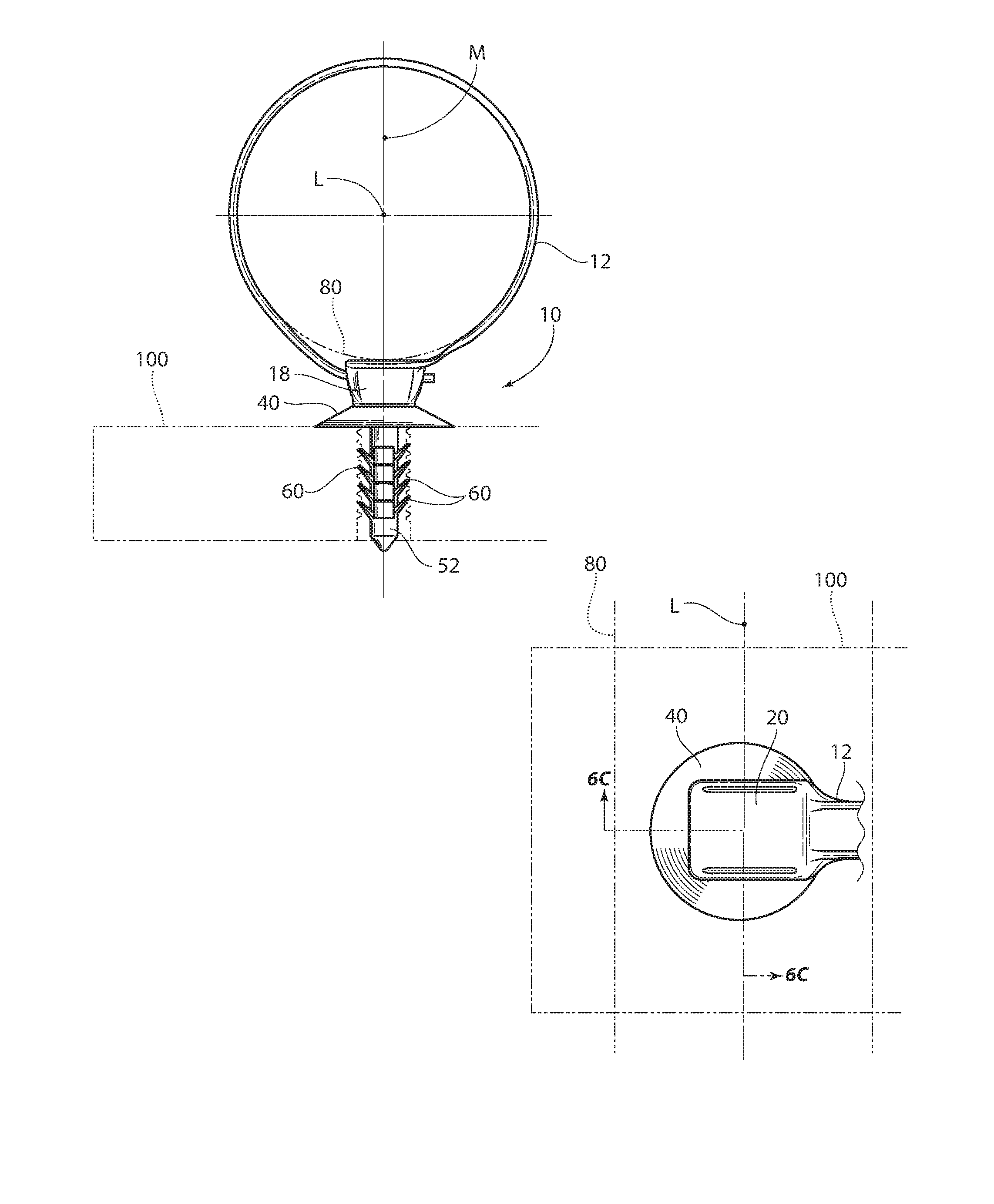
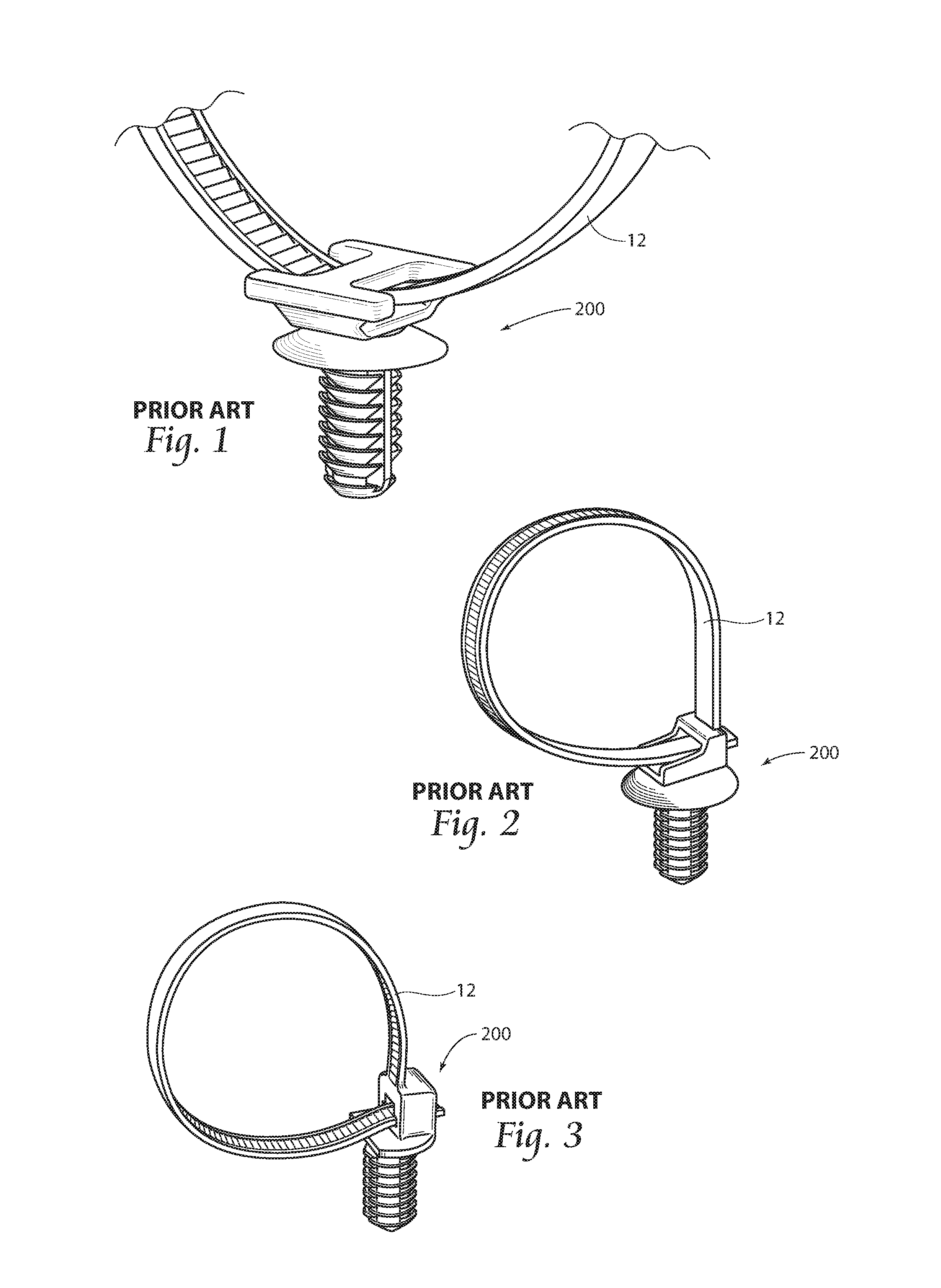
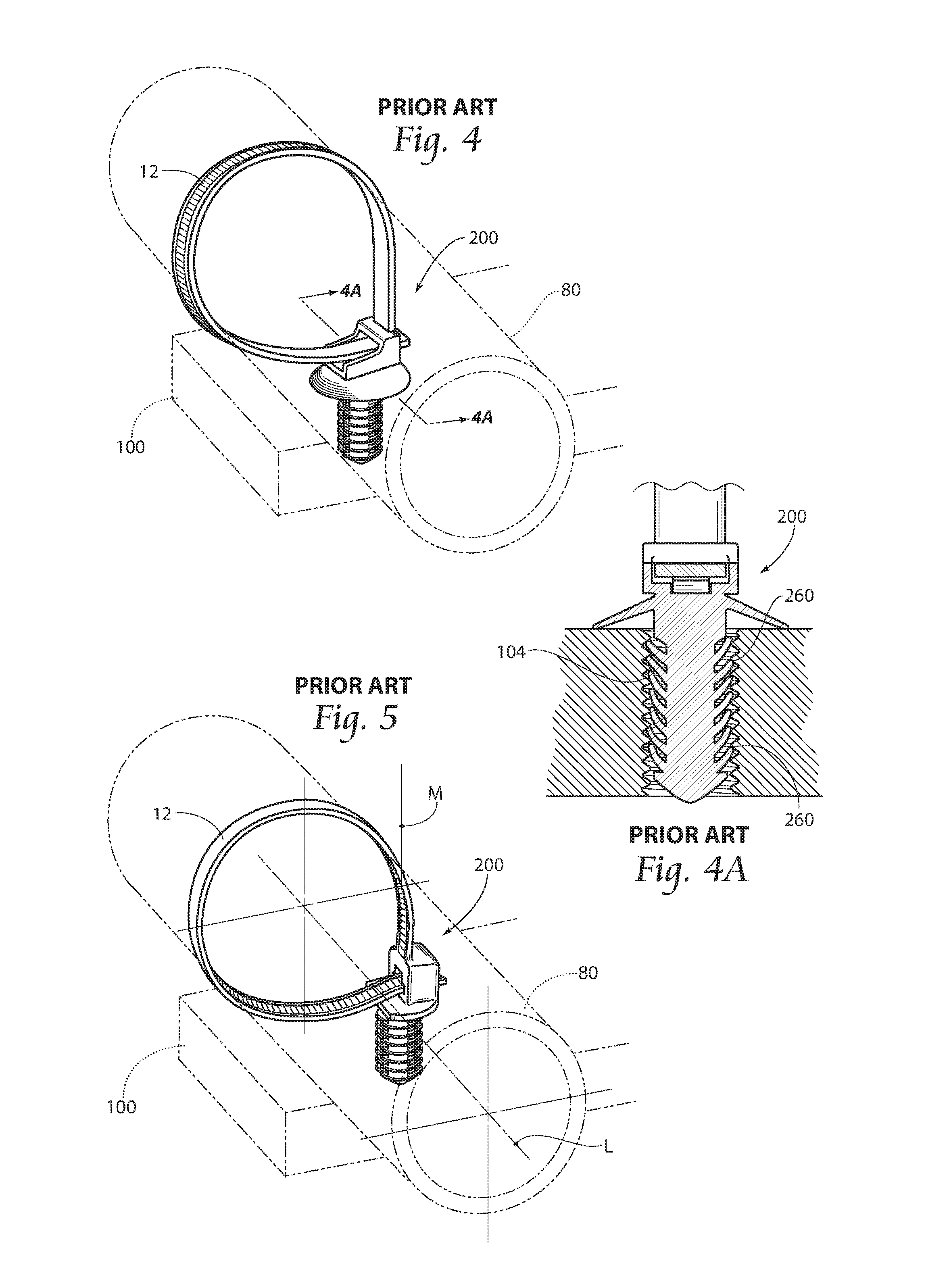
[0039]FIGS. 1-5B illustrate prior art mounting devices 200 which either include an integrally formed cable tie 12 or demonstrate use in conjunction with a cable tie 12. As seen particularly in FIGS. 5, 5A, and 5b, known devices 200 are not typically arranged to self-center the longitudinal axis L of a bundle 80 with the vertical axis M of a mount stud in a mounting bore. As shown, particularly in FIGS. 5A and 5B, the offset distance (OD) changes when the bundle diameter changes. Further, prior art mounts 200 having an offset arrangement and branched mounting sections may not provide adequate attac...


PUM


Abstract

The disclosed device provides an improved mounting assembly for supporting elongated items or bundles against a support surface having a bore. The assembly provides a mount including an integrally formed flexible tie for retaining the items. The tie includes a hinge member to allow the tie to encircle the elongate items, to apply an even circumferential force against the items, and to align the items with the bore. The tie further includes an aperture having a pawl, which engages the flexible strap when it is inserted in the aperture to secure the elongate items. The device also includes a mounting stud having a plurality of branch rows, each row including a plurality of longitudinally spaced branches. The branches extend radially outwardly from a center section and each terminates in a distal end, with the distal ends of branches in adjacent branch rows defining an interrupted helical path.

Description

RELATED APPLICATIONS[0001]This application is a continuation-in-part of co-pending U.S. patent application Ser. No. 13 / 738,567, filed 10 Jan. 2013, which is a continuation-in-part of U.S. patent application Ser. No. 13 / 220,308, filed 29 Aug. 2011, now abandoned, which is a continuation-in-part of U.S. patent application Ser. No. 10 / 835,864, filed 30 Apr. 2004, now U.S. Pat. No. 8,028,962, issued 4 Oct. 2011.BACKGROUND OF THE INVENTION[0002]This invention relates generally to fasteners for securing bundled elongate articles, such as wires, cables, hoses, tubing, fiber optics, conduits, vines, harnesses, etc., to a supporting structure. More particularly, the invention relates to a bundle retention device for securing elongated articles, extending from and through the fastener along the supporting structure or mounting surface.[0003]Flexible cable ties are widely used to secure elongate items, such as wires, cables, hoses and tubes, into compact, secure bundles. Typically, such cable ...

Claims


Application Information

Patent Timeline
Patent Type & Authority Applications(United States)
IPC IPC(8): F16L3/137B65D63/10
CPCF16L3/137B65D63/1027B65D2563/108F16B21/086F16L3/2332F16L3/12F16L3/127F16L3/13F16B21/088F16B5/0685H02G3/32
Inventor GEIGER, GERARD G.
Owner HELLERMANNTYTON CORP
Why Eureka
Try Eureka