Eureka AIR delivers breakthrough ideas for toughest innovation challenges, trusted by R&D personnel around the world.

Optical fiber device

Inactive Publication Date: 2016-08-04
USHIO DENKI KK
View PDF2 Cites 1 Cited by
  • Summary
  • Abstract
  • Description
  • Claims
  • Application Information

AI Technical Summary

Benefits of technology

The optical fiber device in this invention helps to efficiently direct laser light onto its core. This results in better performance of the device.

Problems solved by technology

When the position alignment is not sufficient, for example, the laser light is incident on a clad located outside the core and the clad formed of resin and the like might get burned.
There is also a case in which the incident surface of the core is damaged due to contact of the diaphragm unit and the like with the incident surface of the core at the time of the position alignment, for example.

Method used


Image

  • Optical fiber device
  • Optical fiber device
  • Optical fiber device

Examples


Embodiment Construction

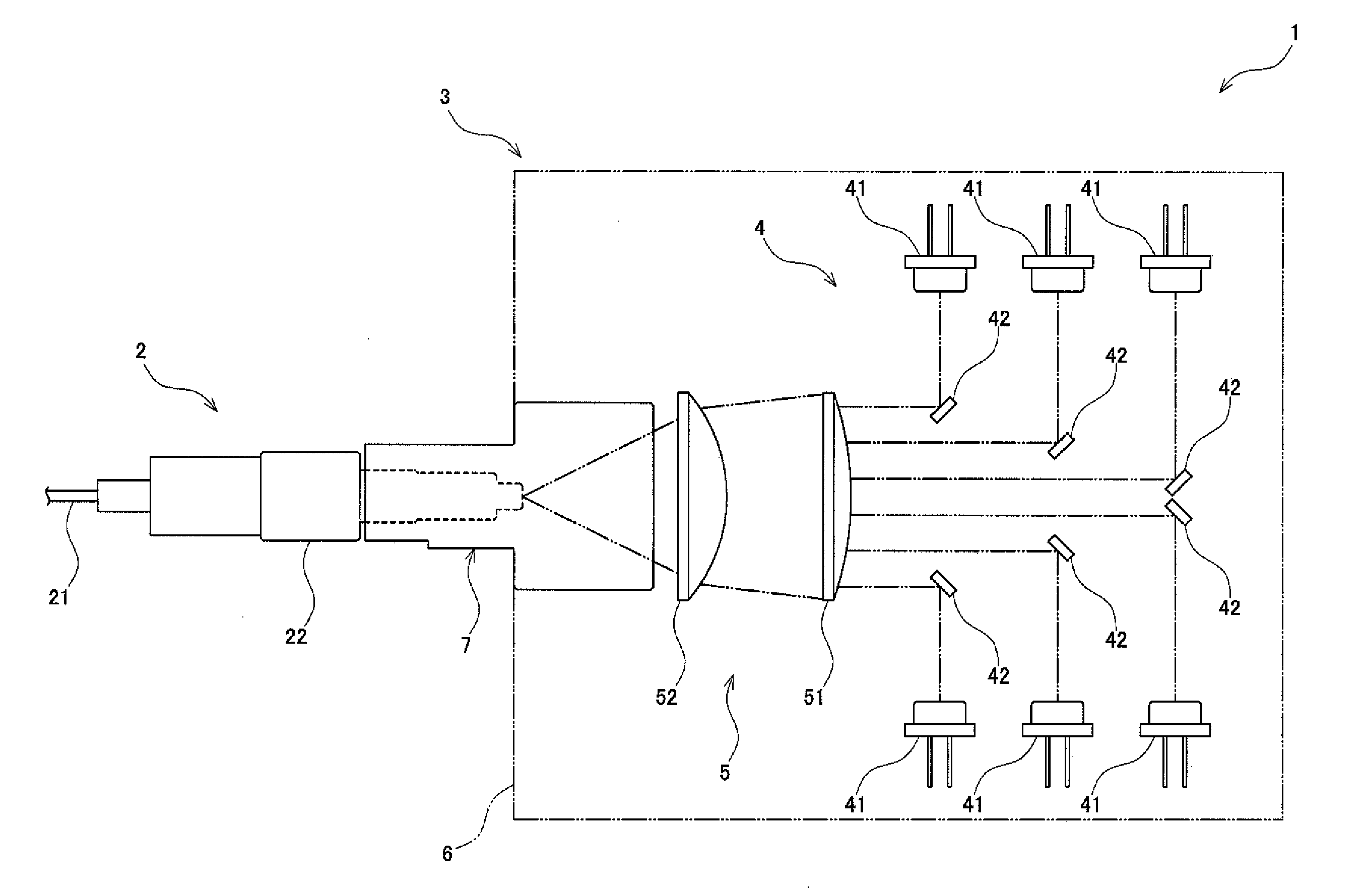
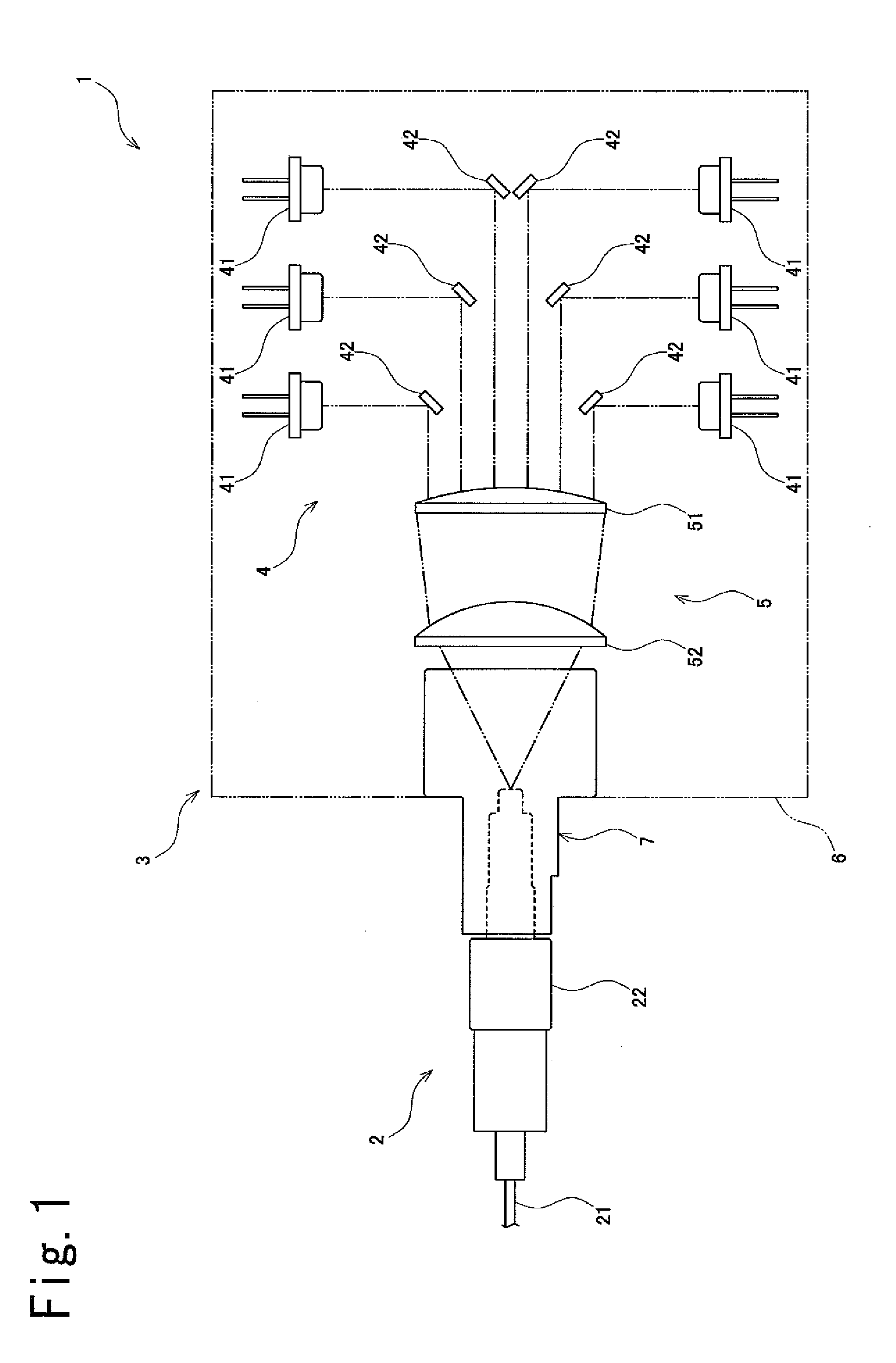
[0028]One embodiment of an optical fiber device according to the present invention is hereinafter described with reference to FIGS. 1 to 5.

[0029]As illustrated in FIG. 1, an optical fiber device 1 according to this embodiment is provided with an optical fiber unit 2 which transmits laser light. The optical fiber device 1 is also provided with a light source device 3 which exits the laser light toward the optical fiber unit 2.

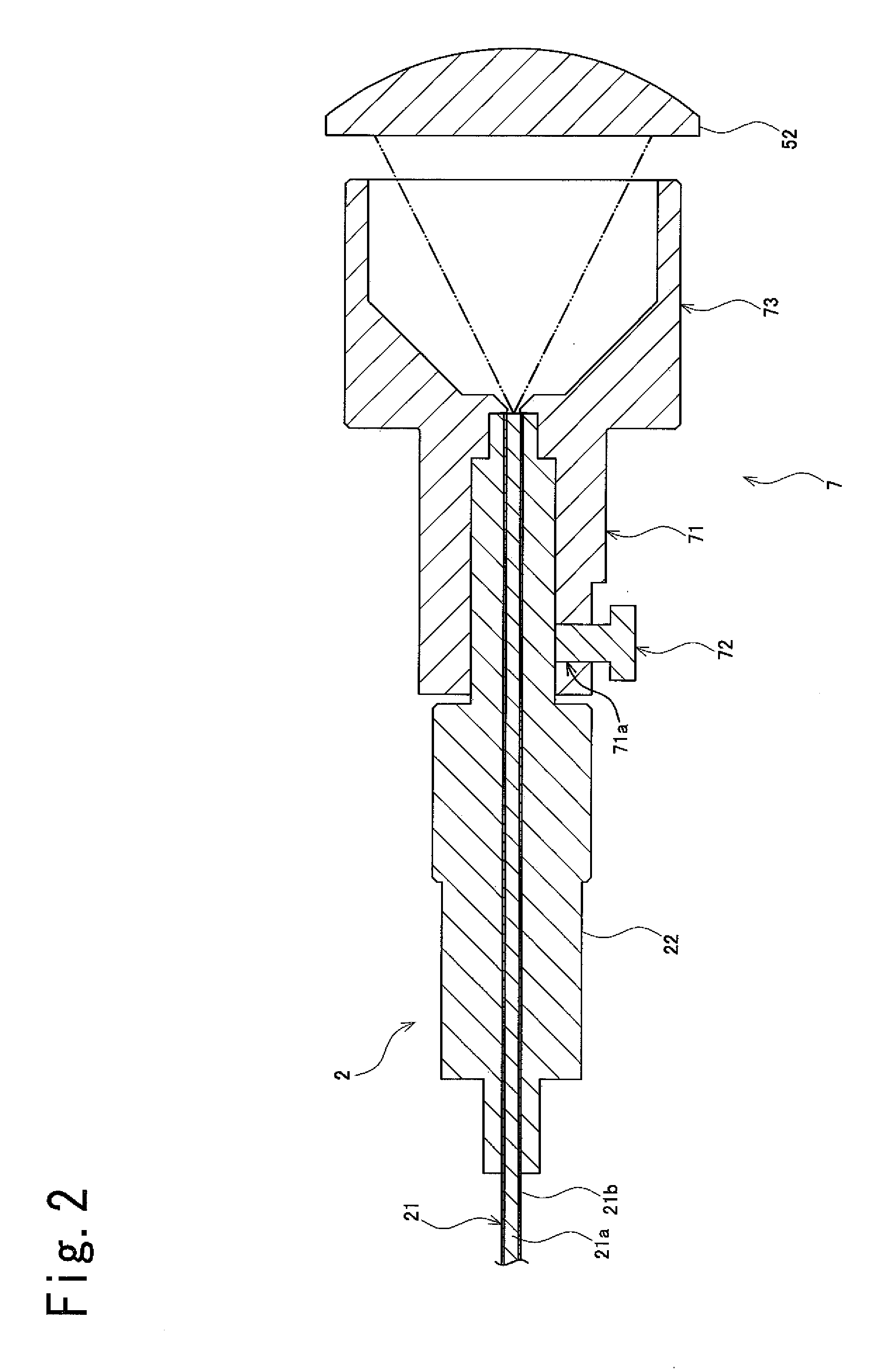
[0030]The optical fiber unit 2 is provided with an optical fiber 21 which transmits the laser light and a ferrule 22 in which the optical fiber 21 is arranged so as to be held and fixed as illustrated in FIGS. 2 and 3. The optical fiber 21 is provided with a core 21a arranged on a central portion thereof to transmit the laser light and a clad 21b having a refractive index lower than that of the core 21a arranged outside the core 21a.

[0031]The core 21a is formed to have a circular cross-sectional shape, specifically, a perfectly circular cross-sectional shape. T...


PUM


Abstract

In an optical fiber device (1), a fiber connection unit is provided with a laser light path unit (73) formed into a hollow shape such that a laser light incident on the core (21a) passes through an interior of the laser light path unit, the laser light path unit (73) is provided with a diaphragm unit (73b) formed to have an inner width dimension smaller than an outer width dimension of the core (21a), and a touching portion (73c) formed to have an inner width dimension larger than the outer width dimension of the core (21a) so as to touch a portion outside the core (21a) on an end face on an incident side of the optical fiber unit (2), the touching portion (73c) arranged on an end on a downstream side.

Description

TECHNICAL FIELD[0001]The present invention relates to an optical fiber device provided with an optical fiber unit including a core which transmits laser light on a central portion thereof.BACKGROUND ART[0002]An optical fiber device provided with an optical fiber unit including a core which transmits laser light on a central portion thereof and a laser light path unit formed into a hollow shape such that the laser light incident on the core passes through an interior thereof is conventionally known as the optical fiber device (for example, Patent Document 1). In such optical fiber device, the laser light path unit is provided with a diaphragm unit, so that the laser light which is not incident on the core is blocked by the diaphragm unit.[0003]Position alignment between an incident surface of the optical fiber unit and the diaphragm unit is required for the laser light to be efficiently incident on the core. When the position alignment is not sufficient, for example, the laser light ...

Claims


Application Information

Patent Timeline
IPC IPC(8): G02B6/42G02B6/43H01S5/40G02B6/32
CPCG02B6/42H01S5/02284H01S5/4012G02B6/43G02B6/4206G02B6/4292G02B6/32G02B6/4214G02B6/424G02B6/00H01S5/02251
Inventor MURAKAMI, SATOSHIFUKUDA, SATORU
Owner USHIO DENKI KK
Why Eureka
Eureka Blog
Learn More