Peak detection method

a detection method and detection method technology, applied in the field ofpeak detection methods, can solve the problems of not always producing a satisfactory effect, difficult to accurately detect peaks, and difficult to equally improve the accuracy of peak detection for a variety of samples, and achieve the effect of accurate detection

Inactive Publication Date: 2016-08-04
SHIMADZU CORP
View PDF2 Cites 17 Cited by
  • Summary
  • Abstract
  • Description
  • Claims
  • Application Information

AI Technical Summary

Benefits of technology

[0042]By the peak detection method according to the present invention, the negative peaks which cannot be handled by the conventional wavelet ridge line detection method can be correctly detected. The peaks can be accurately detected even when there are a plurality of peaks located close to each other or when the signal waveform has a seemingly peak-like portion which actually has resulted from a low-pass filtering process performed on white noise.

Problems solved by technology

However, such a method has the problem that it is difficult to correctly detect a peak if there is a change in the baseline (as shown in FIG. 5A) or if a considerable amount of noise is superposed (as shown in FIG. 5B).
However, such a process does not always produce a satisfactory effect.
However, in the case of a metabolic analysis, a biomarker search or similar analysis in which a considerable number of samples need to be almost continuously analyzed, it is difficult to set the peak detection parameters for each sample, which means that it is difficult to equally improve the accuracy of the peak detection for a variety of samples.

Method used


Image

  • Peak detection method
  • Peak detection method
  • Peak detection method

Examples


Embodiment Construction

[0052]One example of the peak detection method according to the present invention is hereinafter described with reference to the attached drawings.

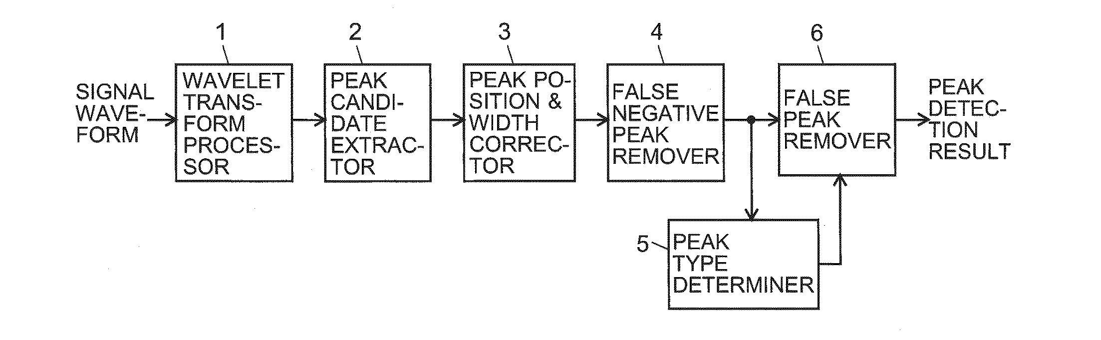
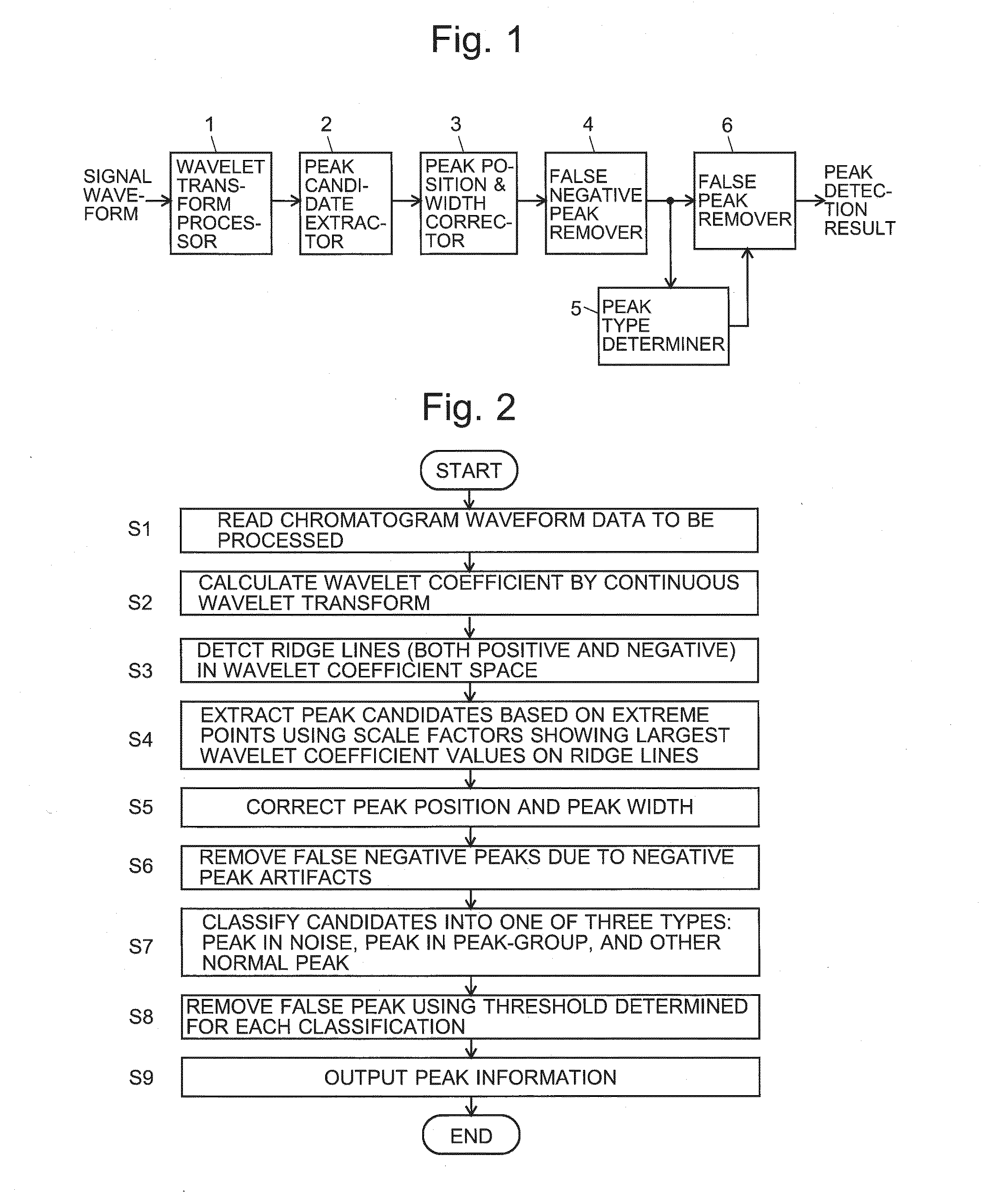
[0053]FIG. 1 is a block configuration diagram showing one embodiment of the peak detection system which carries out a peak detection method according to the present invention. FIG. 2 is a flowchart showing the process flow of the peak detection method carried out by the same system.

[0054]As shown in FIG. 1, the peak detection system of the present embodiment includes a wavelet transform processor 1 which receives a signal waveform to be processed, a peak candidate extractor 2, a peak position and width corrector 3, a false negative peak remover 4, a peak type determiner 5 and a false peak remover 6. By this system, information on the peaks detected on the signal waveform is outputted.

[0055]In the present example, the signal waveform to be processed for the peak detection is a chromatogram waveform obtained with a commonly used liquid chro...


PUM


Abstract

For a signal waveform to be processed, the continuous wavelet transform is performed with various scale factors, and a wavelet coefficient at each point in time is calculated. On an image showing the strength of the wavelet coefficient with respect to the scale factor and time, ridge lines are detected, and based on these ridge lines, positive and negative peak candidates are extracted, after which an error in the position and width of the peak due to the influence of a neighboring peak is corrected. Subsequently, the degree of non-symmetry of the peak shape or other features are examined to remove false negative peaks due to negative peak artifacts. Subsequently, a true peak cluster, a false peak cluster resulting from the removal of high-frequency components of a high-frequency noise or other causes, and other kinds of peaks are identified, and the obtained result is used to remove false peaks.

Description

TECHNICAL FIELD[0001]The present invention relates to a peak detection method for detecting a peak which appears on a signal waveform, such as a chromatogram obtained by a chromatographic analysis or a profile spectrum obtained by a mass spectrometry.BACKGROUND ART[0002]On a chromatogram obtained by a chromatographic analysis, such as a gas chromatography or liquid chromatography, a peak corresponding to a component contained in a sample appears. Normally, the position (time) where the peak appears depends on the kind of compound, while the size of the peak (i.e. its height or area) depends on the amount or concentration of the component corresponding to the peak. Therefore, in order to identify a component in a sample by using a chromatogram, it is important to accurately determine the position of the peak. Similarly, in order to comprehend the amount or concentration of a component in a sample, it is important to accurately determine the height or area of the peak. In any cases, t...

Claims


Application Information

Patent Timeline
Patent Type & Authority Applications(United States)
IPC IPC(8): G06K9/00
CPCG01N30/8634G06K9/00516G06K9/0053G06F2218/10G06F2218/06
Inventor NODA, AKIRAKOZAWA, HIROAKI
Owner SHIMADZU CORP
Why Eureka
Try Eureka