Secondary battery pack having battery cells mounted in cartridge frame

Active Publication Date: 2016-08-04
LG ENERGY SOLUTION LTD
View PDF4 Cites 2 Cited by
  • Summary
  • Abstract
  • Description
  • Claims
  • Application Information

AI Technical Summary

Benefits of technology

The secondary battery pack in this patent is designed to improve its strength and safety. The battery cells are located within a cartridge frame, which protects the outer circumference of the battery pack and also keeps the cells isolated from each other, reducing interference between them.

Problems solved by technology

As a result, the lithium secondary battery may be heated or explode due to overcharge of the lithium secondary battery, overcurrent in the lithium secondary battery, or other external physical impact applied to the lithium secondary battery.
That is, the safety of the lithium secondary battery is very low.
In particular, much interest is currently focused on the pouch-shaped battery, which uses an aluminum laminate sheet as a sheathing member, since the pouch-shaped battery is lightweight and the manufacturing cost of the pouch-shaped battery is low.
When a battery module or a battery pack is manufactured using pouch-shaped batteries as described above, however, various difficulties and problems are caused during connection between electrode terminals of the pouch-shaped batteries by welding.
In these structures, however, the number of parts is increased with the result that manufacturing cost is increased and a manufacturing processability is lowered.

Method used


Image

  • Secondary battery pack having battery cells mounted in cartridge frame
  • Secondary battery pack having battery cells mounted in cartridge frame
  • Secondary battery pack having battery cells mounted in cartridge frame

Examples


Embodiment Construction

[0040]Now, preferred embodiments of the present invention will be described in detail with reference to the accompanying drawings. It should be noted, however, that the scope of the present invention is not limited by the illustrated embodiments.

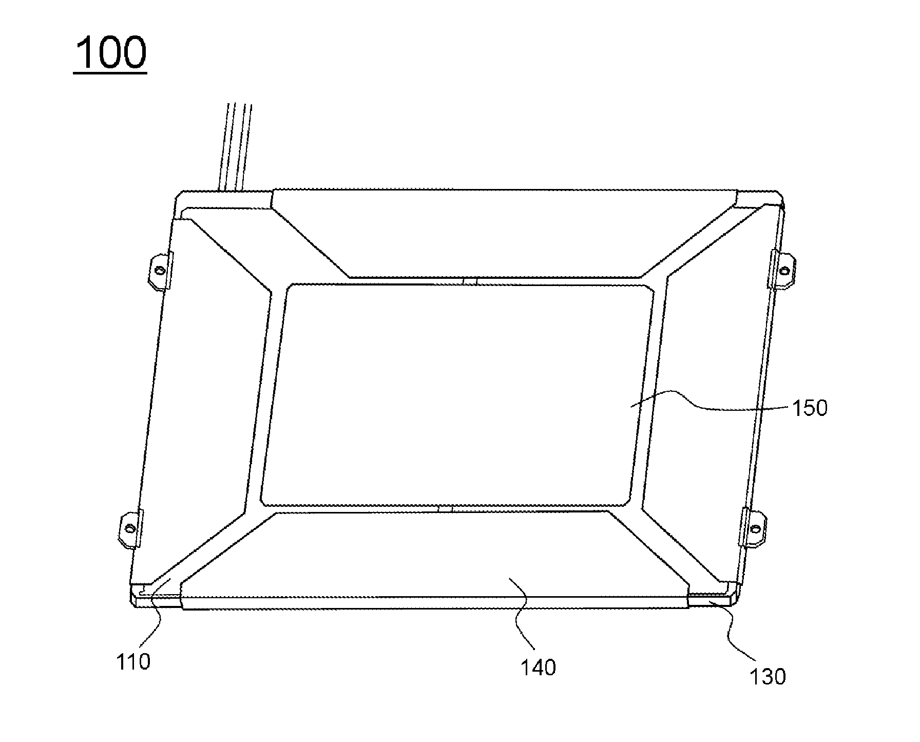
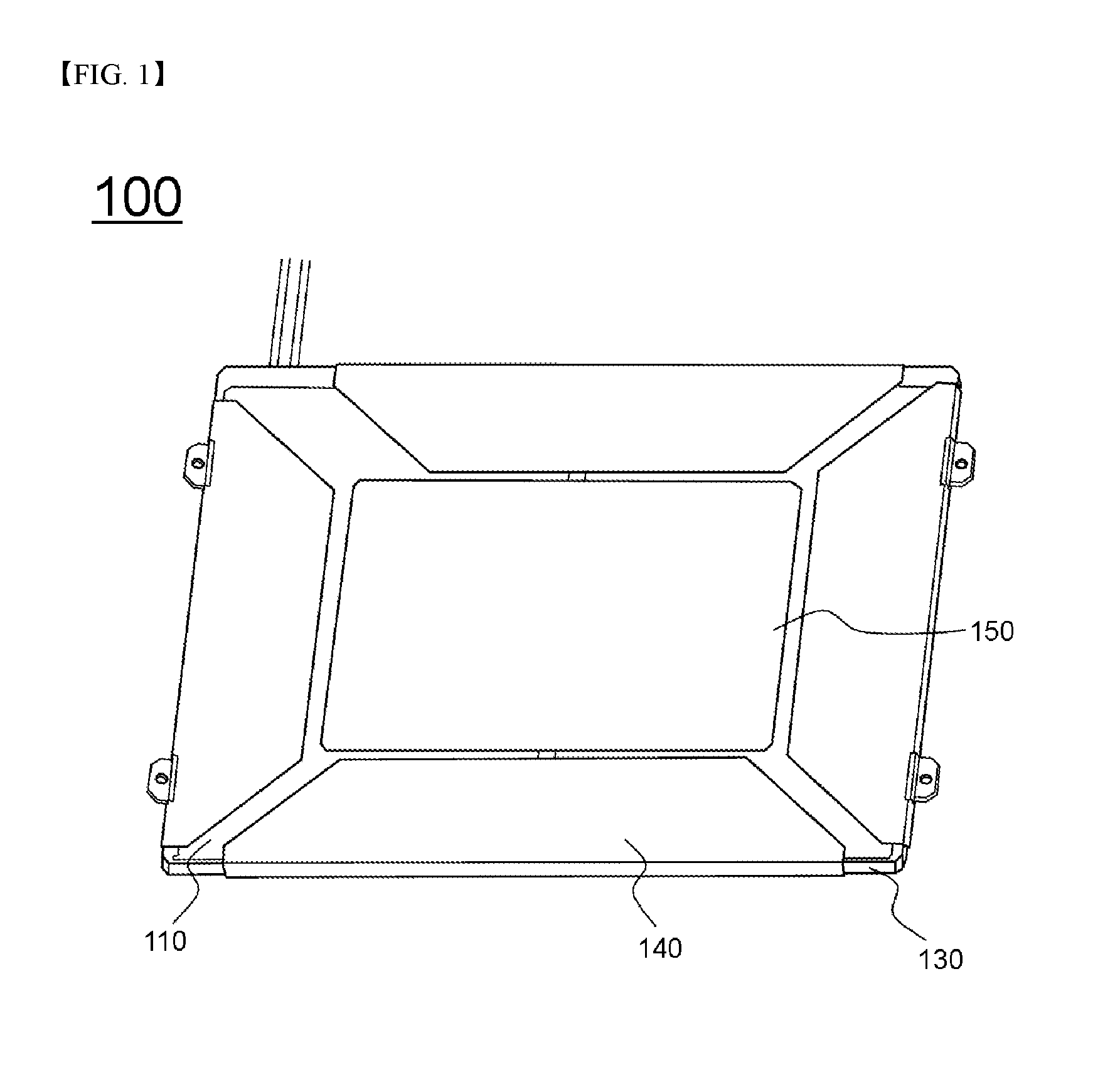
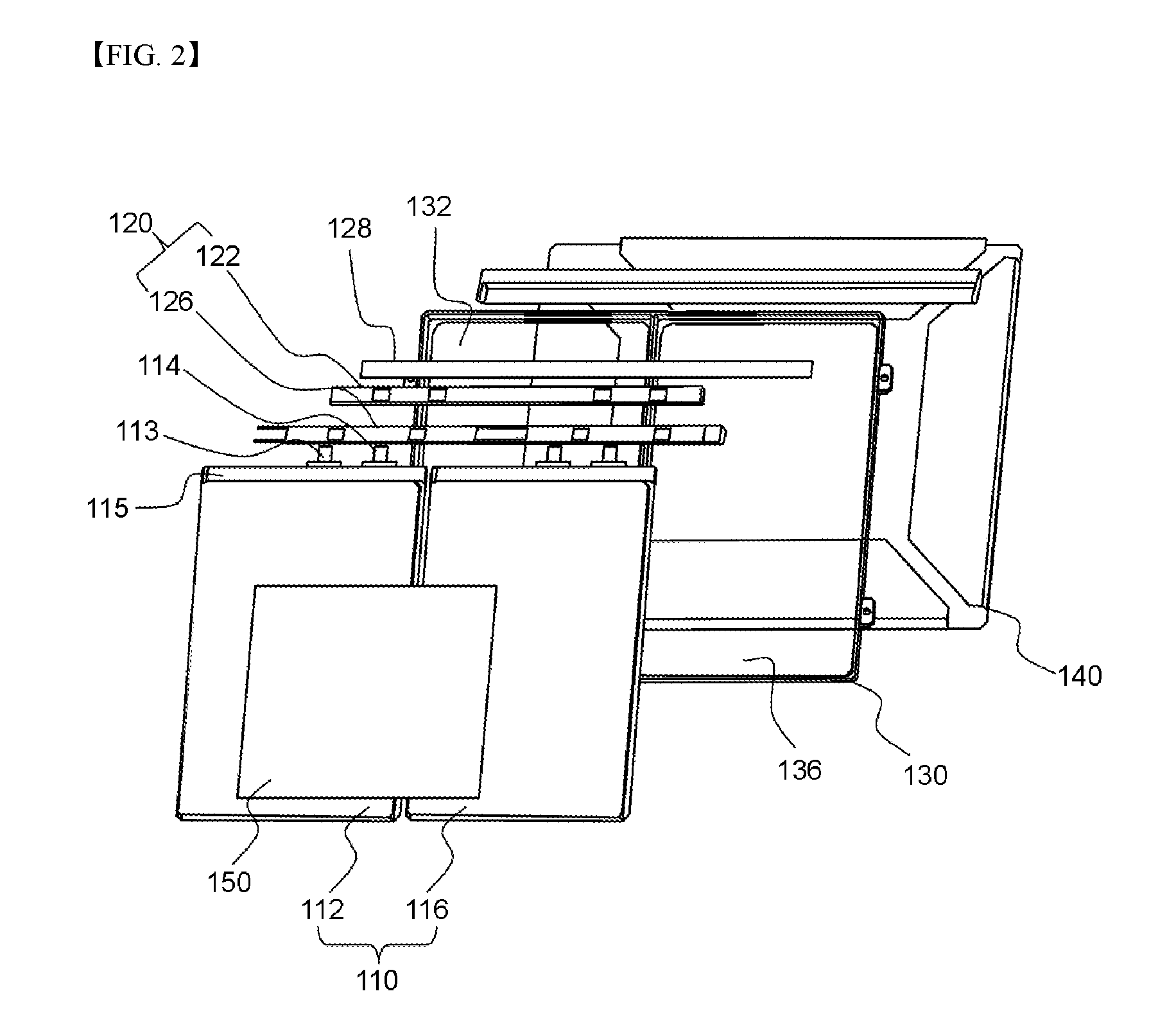
[0041]FIG. 1 is a typical view showing a secondary battery pack according to an embodiment of the present invention and FIG. 2 is an exploded perspective view of the secondary battery pack shown in FIG. 1.

[0042]Referring to FIGS. 1 and 2, the secondary battery pack 100 is configured to have a structure including a battery cell array 110, a protection circuit module (PCM) 120, a cartridge frame 130, and a sheathing label 140.

[0043]The battery cell array 110 is configured to have a structure in which two battery cells 112 and 116, each of which includes electrode terminals 113 and 114 formed at one side thereof and a thermally bonded surplus portion 115 formed at the side thereof at which the electrode terminals 113 and 114 are formed, are arr...


PUM


Abstract

Disclosed herein is a secondary battery pack including a battery cell array configured to have a structure in which two or more battery cells, each of which includes electrode terminals formed at one side thereof and a thermally bonded surplus portion formed at the side thereof at which the electrode terminals are formed, are arranged side by side, a protection circuit module (PCM) configured to have a structure including a protection circuit board (PCB) having a protection circuit formed thereon, an external input and output terminal connected to the protection circuit of the PCB, and a PCM case, in which the PCB is mounted, the PCM being loaded on the thermally bonded surplus portions of the battery cells in a state in which the PCM is electrically connected to the battery cells, a cartridge frame including two or more battery cell location parts for fixing the two battery cells, respectively, each of the battery cell location parts being formed in a frame shape corresponding to an outer circumference of a corresponding one of the battery cells, and a sheathing label attached to the cartridge frame such that the sheathing label wraps the cartridge frame in a state in which the battery cells, to which the PCM is connected, are fixed in the cartridge frame.

Description

TECHNICAL FIELD[0001]The present invention relates to a secondary battery pack including battery cells mounted in a cartridge frame and, more particularly, to a secondary battery pack including a battery cell array configured to have a structure in which two or more battery cells, each of which includes electrode terminals formed at one side thereof and a thermally bonded surplus portion formed at the side thereof at which the electrode terminals are formed, are arranged side by side, a protection circuit module (PCM) configured to have a structure including a protection circuit board (PCB) having a protection circuit formed thereon, an external input and output terminal connected to the protection circuit of the PCB, and a PCM case, in which the PCB is mounted, the PCM being loaded on the thermally bonded surplus portions of the battery cells in a state in which the PCM is electrically connected to the battery cells, a cartridge frame including two or more battery cell location par...

Claims


Application Information

Patent Timeline
IPC IPC(8): H01M2/10H01M2/20H01M10/0585H01M10/42H01M10/0525H01M50/105H01M50/211H01M50/247H01M50/262H01M50/291H01M50/296H01M50/503H01M50/512H01M50/519H01M50/572
CPCH01M2/1066H01M10/052H01M10/4221H01M2220/30H01M2/1022H01M10/4257H01M10/425H01M2/204H01M10/0525H01M10/0585H01M2/1061Y02E60/10Y02P70/50H01M50/105H01M50/247H01M50/512H01M50/503H01M50/572H01M50/211H01M50/262H01M50/519H01M50/291H01M50/296H01M50/183H01M50/147
Inventor KIM, HAN CHULLEE, DONG CHEOL
Owner LG ENERGY SOLUTION LTD
Why Eureka
Try Eureka