
Structure of wing-knob for air vent

a technology for air vents and wing knobs, which is applied in vehicle components, vehicle heating/cooling devices, transportation and packaging, etc., can solve problems such as deformation, damage, and deformation, and achieve the effect of minimizing post deformation and suppressing the occurrence of breakag

Active Publication Date: 2016-08-11
HYUNDAI MOTOR CO LTD
View PDF7 Cites 7 Cited by
  • Summary
  • Abstract
  • Description
  • Claims
  • Application Information

AI Technical Summary

Benefits of technology

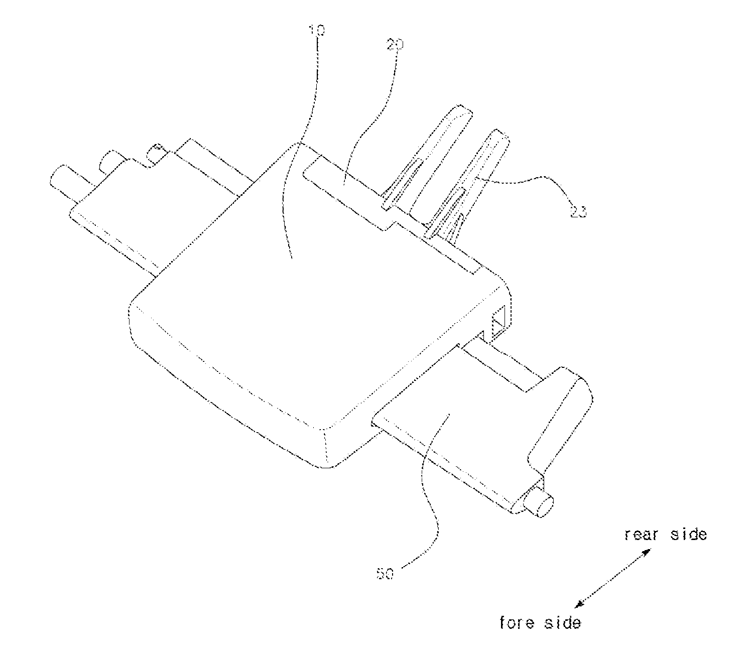
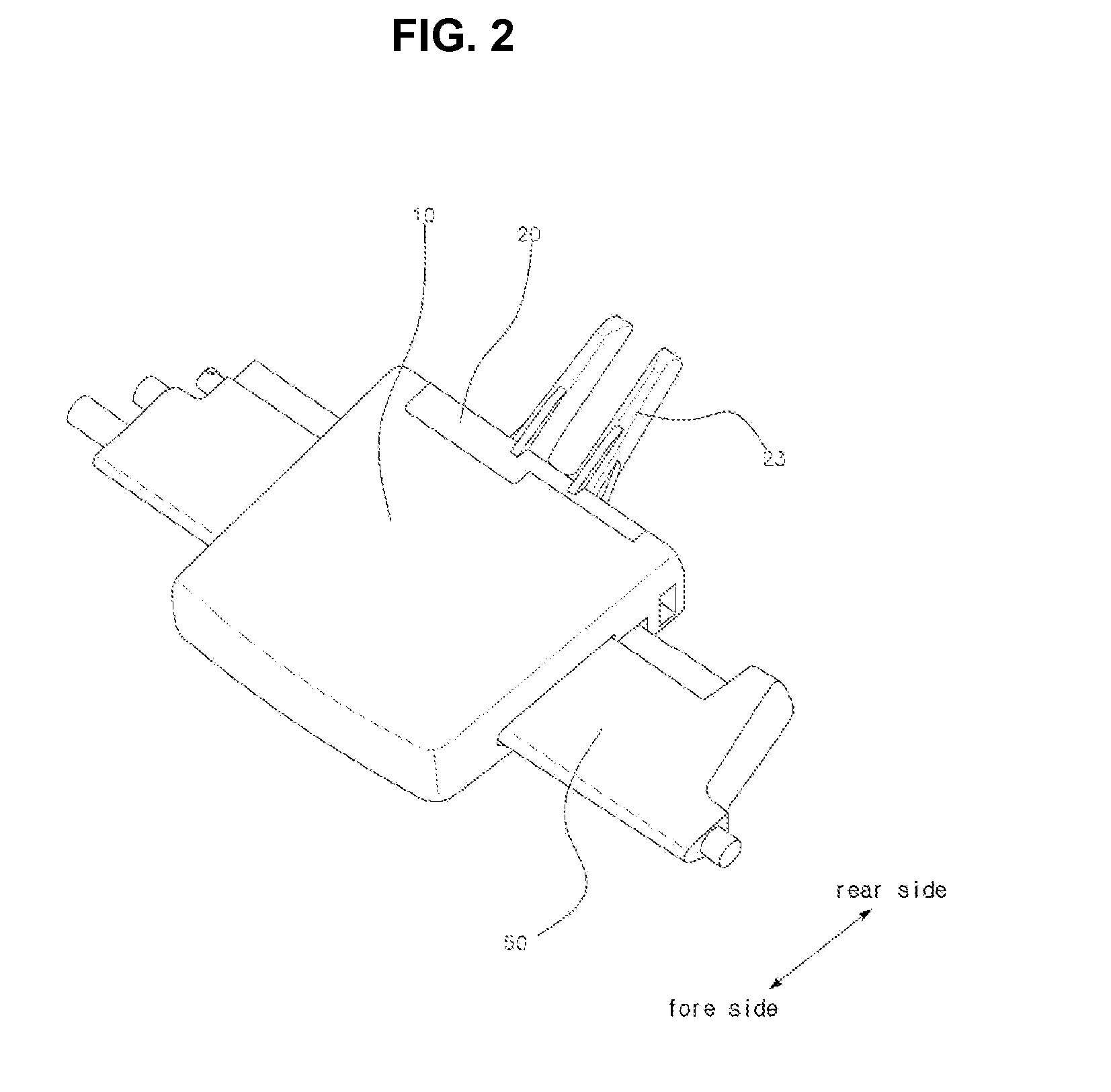
The present invention aims to provide a wing knob for air vent that can prevent breakage and minimize post-deformation after injection molding. The invention achieved this by designing a structure that prevents stress concentration at the conventional hook and by opening the insertion hole only in lateral direction.

Problems solved by technology

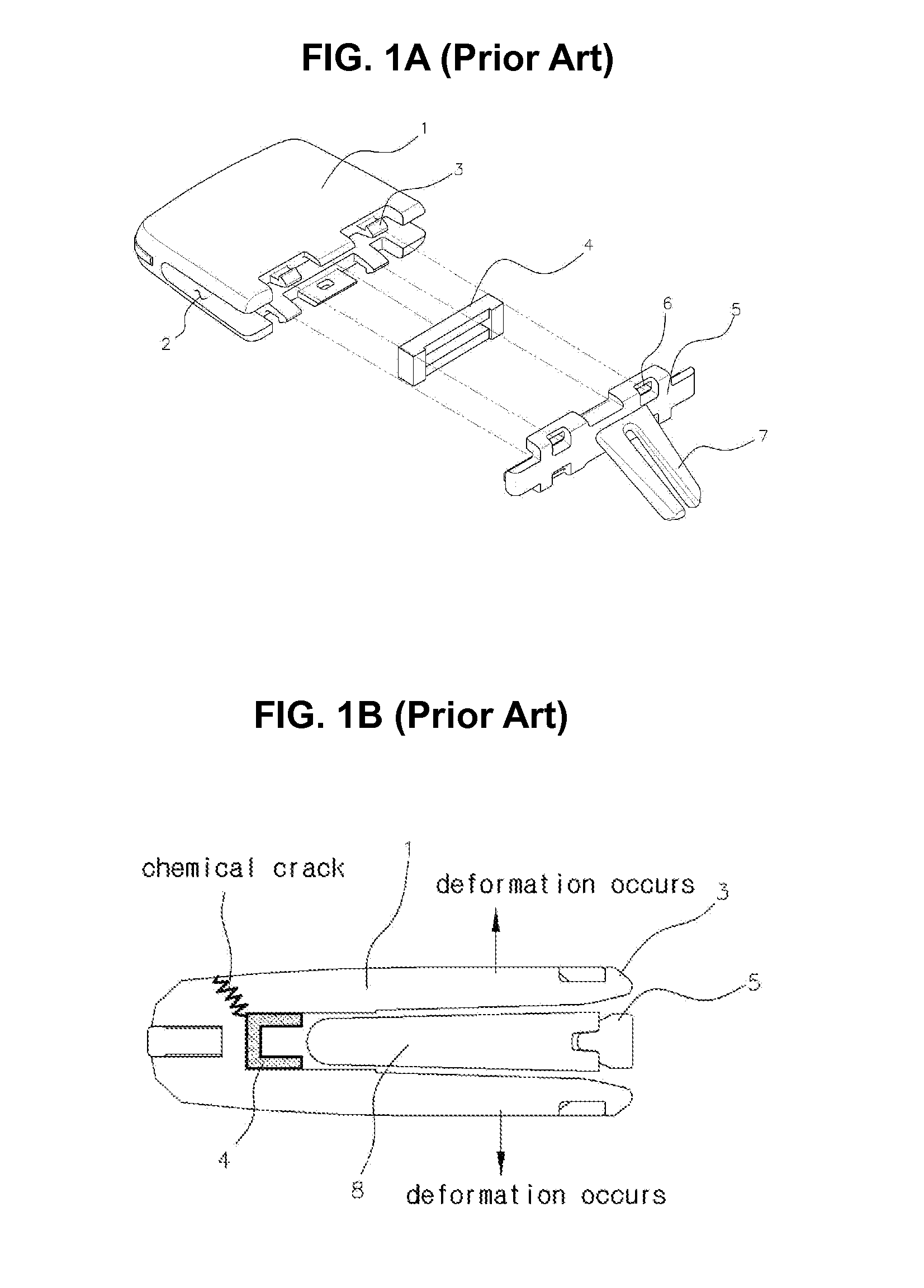
However, since the knob body 1 is operated (in the upward-downward direction and the left-right direction) under the condition that the blade 8 is inserted into the insertion hole 2, there is a problem in that the stress is accumulated near the place of combination of the hook 3 and the hole 6 so that the deformation occurs as shown in FIG. 1B.
In addition, there can occur the problem in that a chemical crack occurs due to the repeated friction and the chemical reaction between the oil and the knob body 1 so that the front side of the knob body 1 is broken.
Furthermore, the knob body 1 and the rear cover 5 manufactured with the synthetic resin by being injection molded have difficulty in maintaining the shape and size of the insertion hole 2, hook 3 and hole 6 to be uniform due to the manufacturing process (due to the post deformation occurring at the time of cooling after injection molding).
In addition, an indicator (not shown) (indicating the possible direction of sliding) and the like may be additionally inserted into the insertion hole 2 in the knob body 1 before the combination of the blade 8, however, there could occur a problem in that the inlet portion of the insertion hole 2 is stretched wide at the time of assembly of the indicator and the silicon rubber 4 so as to cause the deformation and the damage.

Method used


Image

  • Structure of wing-knob for air vent
  • Structure of wing-knob for air vent
  • Structure of wing-knob for air vent

Examples


Embodiment Construction

[0034]Reference will now be made in detail to various embodiments of the present invention(s), examples of which are illustrated in the accompanying drawings and described below. While the invention(s) will be described in conjunction with exemplary embodiments, it will be understood that the present description is not intended to limit the invention(s) to those exemplary embodiments. On the contrary, the invention(s) is / are intended to cover not only the exemplary embodiments, but also various alternatives, modifications, equivalents and other embodiments, which may be included within the spirit and scope of the invention as defined by the appended claims.

[0035]The present invention relates to a structure of wing knob for an air vent in which an insertion hole is formed, and two latching pins are protruded, and either one among a vertical blade and a horizontal blade arranged in the front side and the rear side is inserted into the insertion hole, and the other one is inserted betw...


PUM


Abstract

A structure of a wing knob for an air vent in which an insertion hole is formed, and two latching pins are protruded, and either one among a vertical blade and a horizontal blade arranged in a front side and a rear side is inserted into the insertion hole, and another among the vertical blade and the horizontal blade is inserted between the latching pins may include a knob body at which is formed the insertion hole through one side of which either one blade among the vertical blade and the horizontal blade penetrates and is inserted, and at a rear side is formed an opening hole, and a rear cover at a front side of which is combined a left-right stopper and at a rear side of which is formed latching pins.

Description

CROSS-REFERENCE TO RELATED APPLICATION[0001]The present application claims priority to Korean Patent Application No. 10-2015-0020755 filed Feb. 11, 2015 the entire contents of which is incorporated herein for all purposes by this reference.BACKGROUND OF THE INVENTION[0002]1. Field of the Invention[0003]The present invention relates to a structure of wing knob for air vent provided in the car cabin. More particularly, the present invention relates to a structure of wing knob for air vent which can suppress the occurrence of damage caused by stress concentration.[0004]2. Description of Related Art[0005]An air conditioning system is mounted on the car to maintain the temperature, humidity and the like in the car cabin to be comfortable.[0006]The air conditioning system comprises an air conditioner which supplies cold air by using the phase change of coolant, and a heater supplying hot air by using the heat of the cooling water heated at the engine, and the cold air and hot air produced...

Claims


Application Information

Patent Timeline
IPC IPC(8): B60H1/00
CPCB60H1/0065B60H2001/00721B60H1/00671B60H1/34B60H2001/3471B60H1/3414
Inventor KWON, HYUK-JAE
Owner HYUNDAI MOTOR CO LTD
Learn More