Hybrid vehicle

a hybrid vehicle and hybrid technology, applied in the direction of engine-driven generators, automatic control systems, transportation and packaging, etc., can solve the problems of delay in the increase of the torque of the drive shaft, driver may not have a good acceleration feeling, etc., to reduce the delay of the increase of the drive shaft torque, and increase the rotation number of the engine and the torque

Active Publication Date: 2016-08-11
TOYOTA JIDOSHA KK
View PDF2 Cites 6 Cited by
  • Summary
  • Abstract
  • Description
  • Claims
  • Application Information

AI Technical Summary

Benefits of technology

[0009]According to the above configuration, the hybrid vehicle sets a running torque based on a required torque of the drive shaft according to the accelerator opening degree, and controls the engine and the motor so that the running torque is output to the drive shaft. When the predetermined acceleration request is made, the power of the engine is limited by use of the running torque or the drive-shaft torque output to the drive shaft as the torque for determination until the torque for determination reaches the torque threshold smaller than the required torque, as compared with the power of the engine after the torque for determination has reached the torque threshold. Accordingly, the power of the engine is limited until the torque for determination reaches the torque threshold, so as to restrain increases of the rotation number of the engine and the torque. After the torque for determination has reached the torque threshold, the limitation on the power of the engine is relaxed or released, so as to increase the rotation number of the engine and the torque. Hereby, it is possible to restrain delay of the increase of the drive-shaft torque with respect to the increase of the rotation number of the engine. As a result, it is possible to give a good acceleration feeling to the driver.
[0010]In the hybrid vehicle, the electronic control unit may be configured to limit the power of the engine by an upper limit power when the predetermined acceleration request is made. The electronic control unit may be configured to set the upper limit power based on a first power until the torque for determination reaches the torque threshold when the predetermined acceleration request is made. The electronic control unit may be configured to set the upper limit power based on a second power after the torque for determination has reached the torque threshold when the predetermined acceleration request is mad. The first power may be larger one of a value of zero and a power corresponding to a difference between a running power corresponding to the running torque and an allowable output power of the battery. The second power may be a power gradually approaching a third power according to the running power and a required power for charging and discharging the battery. According to the above configuration, when the predetermined acceleration request is made, it is possible to prevent the power of the engine from decreasing as compared with the power before the predetermined acceleration request is made.

Problems solved by technology

At this time, if a rotation number of the engine increases quickly after the accelerator pedal is stepped, an increase of a torque of the drive shaft may be delayed with respect to the increase of the rotation number of the engine, so that the driver may not have a good acceleration feeling.

Method used


Image

  • Hybrid vehicle
  • Hybrid vehicle
  • Hybrid vehicle

Examples


Embodiment Construction

[0030]Next will be described an embodiment with reference to the drawings.

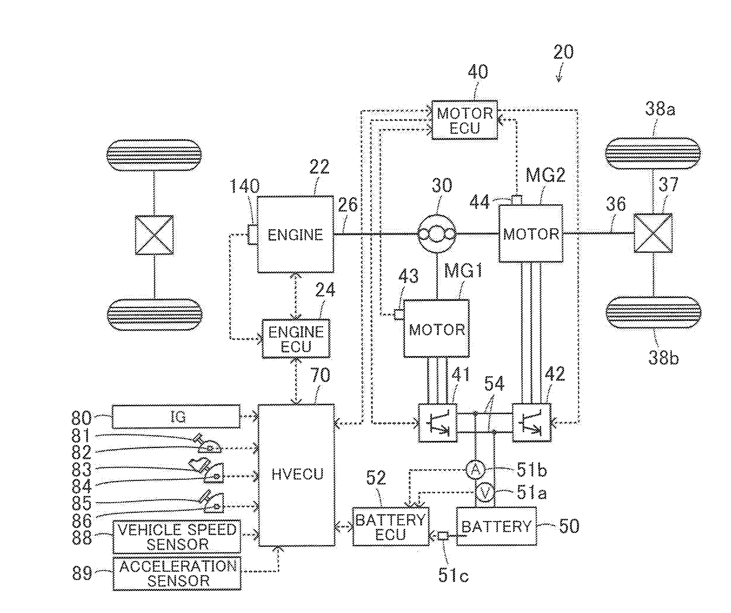
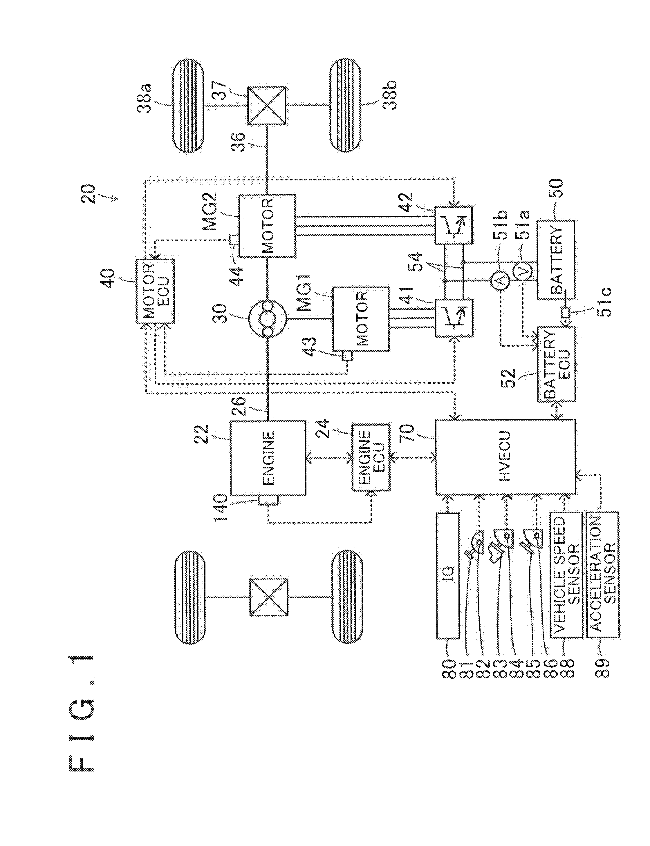
[0031]FIG. 1 is a configuration diagram illustrating an outline of a configuration of a hybrid vehicle 20 according to one embodiment. As illustrated herein, the hybrid vehicle 20 of the embodiment includes an engine 22, a planetary gear 30, motors MG1, MG2, inverters 41, 42, a battery 50, and a hybrid electronic control unit (hereinafter referred to as the “HVECU”) 70.

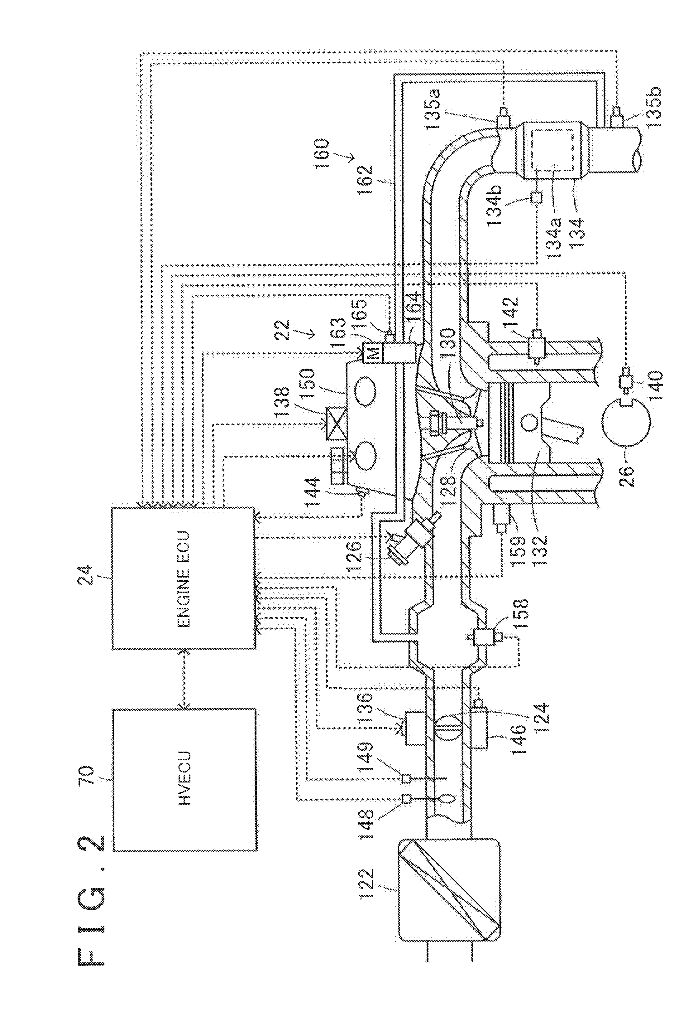
[0032]In the embodiment, the engine 22 is an internal combustion engine that outputs a power by using gasoline or gas oil as fuel. FIG. 2 is a configuration diagram illustrating an outline of a configuration of the engine 22. In the engine 22, air purified by an air cleaner 122 is intaken via a throttle valve 124 and fuel is injected from a fuel injection valve 126, so that the air is mixed with the fuel. The fuel / air mixture is intaken into a combustion chamber via an intake valve 128. In the engine 22, the fuel / air mixture intaken into the com...


PUM


Abstract

A hybrid vehicle includes an engine, a motor, a battery and an electronic control unit. The electronic control unit is configured to set a running torque based on a required torque of a drive shaft according to an accelerator opening degree. The electronic control unit is configured to control the engine and the motor such that the running torque is output to the drive shaft. The electronic control unit is configured to limit the power of the engine by use of the running torque or a drive-shaft torque output to the drive shaft as a torque for determination until the torque for determination reaches a torque threshold smaller than the required torque, as compared with the power of the engine after the torque for determination has reached the torque threshold, when a predetermined acceleration request is made by a user.

Description

INCORPORATION BY REFERENCE[0001]The disclosure of Japanese Patent Application No. 2015-022360 filed on Feb. 6, 2015 including the specification, drawings and abstract is incorporated herein by reference in its entirety.BACKGROUND[0002]1. Technical Field[0003]The disclosure relates to a hybrid vehicle.[0004]2. Description of Related Art[0005]Japanese Patent Application Publication No. 2014-92146 (JP 2014-92146 A) describes a control device for an internal combustion engine including a variable valve timing mechanism and a throttle valve. The variable valve timing mechanism changes a valve timing of an engine valve. The throttle valve adjusts an intake-air amount. The control device controls a valve timing of the engine valve and an opening degree of the throttle valve according to a target torque required to the internal combustion engine. In the control device, when the target torque changes, the variable valve timing mechanism and the throttle valve are controlled so that a timing ...

Claims


Application Information

Patent Timeline
Patent Type & Authority Applications(United States)
IPC IPC(8): B60W20/13B60W10/08B60W10/06B60L50/16
CPCB60W20/13B60W10/06B60W10/08B60W2540/103B60W2710/0666B60W2710/0633B60W2710/083Y10S903/93B60K6/24B60Y2200/92B60W2710/0677B60W2556/00B60K6/445B60W50/06B60W2540/10B60W20/10Y02T10/62
Inventor TAKAHASHI, YOSHIMITSU
Owner TOYOTA JIDOSHA KK
Why Eureka
Try Eureka