Actuating mechanism and gear driven adjustment ring for a variable geometry turbocharger

a variable turbine geometry and actuation mechanism technology, applied in the direction of belt/chain/gearing, friction gearing, belt/chain/gearing, etc., can solve the problems of choking the engine at high speeds, inconvenient adjustment of the adjustment ring, and inability to adjust the ring, so as to reduce the hysteresis

Inactive Publication Date: 2016-08-11
BORGWARNER INC
View PDF7 Cites 9 Cited by
  • Summary
  • Abstract
  • Description
  • Claims
  • Application Information

AI Technical Summary

Benefits of technology

[0008]VGT turbochargers include movable vanes that are located in the turbine housing. The vanes rotate relative to the turbine housing to adjust the amount of exhaust gas flow to the turbine wheel, thereby allowing the turbocharger to operate properly under a wide variety of conditions. When the vanes are closed at low speeds, the exhaust gas is accelerated towards the turbine wheel blades allowing the turbocharger to provide the needed boost. At high speeds, the vanes are open decreasing the exhaust flow towards the turbine wheel blades and adjusting the boost as needed. The VGT turbocharger includes a gear driven adjustment ring actuator mechanism that is configured to precisely move the vanes in the turbine housing with reduced hysteresis as compared to some VGT turbochargers in which the vanes are typically adjusted using a block driven adjustment ring actuator mechanism.
[0009]According to one aspect of the disclosure, a gear driven adjustment ring actuator mechanism is provided for controlling the rotational movement of the adjustment ring of a variable turbine geometry turbine wherein the vanes are moved using a rack gear and pinion system. The rack gear is located relative the adjustment ring such that the teeth of the rack gear are disposed outwardly relative to an outer edge of the adjustment ring. By this arrangement, interference of the rack gear with the complex vane adjustment components is avoided. The rack gear can be formed so that the rack gear teeth face radially inwardly, or alternatively can be formed so that the rack gear teeth face radially outwardly.
[0013]According to another aspect of the disclosure, the rack gear is separate from and then attached to the adjustment ring such that the teeth of the rack gear are disposed at the same radially outward position as the outer edge of the adjustment ring. By forming the rack gear as a separate entity, it can advantageously be formed of a different material than the remainder of the adjustment ring. For example, the rack gear can be formed of a relatively expensive, highly wear resistant material as compared to the remainder of the adjustment ring, whereby durability of the adjustment ring can be improved, and manufacturing costs can be reduced relative to an adjustment ring formed entirely of the highly wear resistant material.

Problems solved by technology

Thus, a larger turbine for a given engine provides good boost at high speeds, but does not do well at low speeds because it suffers turbo lag and is thus unable to provide boost when needed.
A small turbine provides good boost at low speeds, but can choke the engine at high speeds.
Unfortunately, some currently available linkages are imprecise and suffer from hysteresis.

Method used


Image

  • Actuating mechanism and gear driven adjustment ring for a variable geometry turbocharger
  • Actuating mechanism and gear driven adjustment ring for a variable geometry turbocharger
  • Actuating mechanism and gear driven adjustment ring for a variable geometry turbocharger

Examples


Embodiment Construction

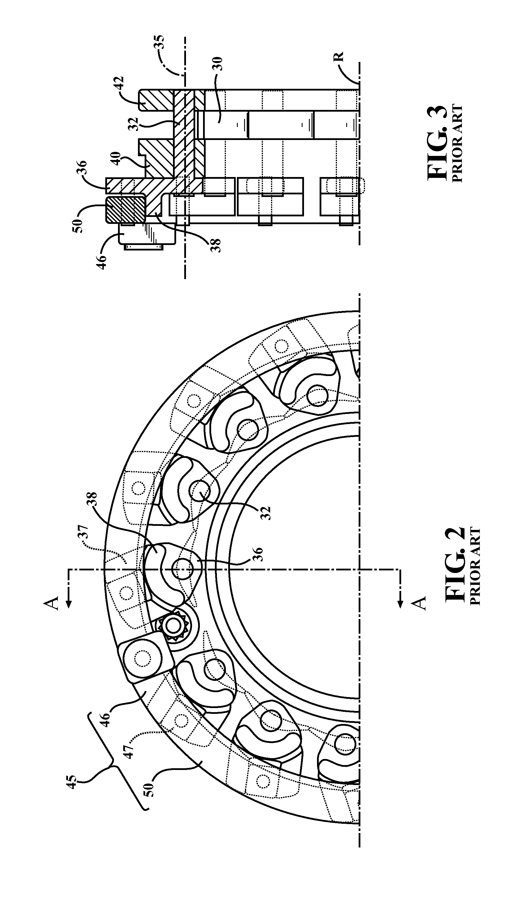
[0031]Referring to FIG. 1, a conventional exhaust gas turbocharger 1 includes a turbine section 2, the compressor section 18, and a center bearing housing 16 disposed between and connecting the compressor section 18 to the turbine section 2. The turbine section 2 includes a turbine housing 4 that defines an exhaust gas inlet (not shown), an exhaust gas outlet 8, and a turbine volute 10 disposed in the fluid path between the exhaust gas inlet and the exhaust gas outlet 8. A turbine wheel 12 is disposed in the turbine housing 4 between the turbine volute 10 and the exhaust gas outlet 8. A shaft 14 is connected to the turbine wheel 12, is supported for rotation about a rotational axis R within in the bearing housing 16, and extends into the compressor section 18. The compressor section 18 includes a compressor housing 20 that defines an axially-extending air inlet 22, an air outlet (not shown), and a compressor volute 26. A compressor wheel 28 is disposed in the compressor housing 20 b...


PUM


Abstract

A variable geometry turbine turbocharger (1) includes a gear driven adjustment ring actuator mechanism (300) supported within a housing (16) via a resilient mount (70) disposed between the mechanism (300) and housing (16). The gear driven adjustment ring actuator mechanism (300) rotates an adjustment ring (350), which in turn adjusts the position of the vanes (30) of the variable geometry turbine (2). The resilient mount (70) accommodates the heat-related expansion and contraction of the gear driven adjustment ring actuator mechanism (300).

Description

CROSS-REFERENCE TO RELATED APPLICATIONS[0001]This application claims priority to and all the benefits of U.S. Provisional Application No. 61 / 884,289, filed on Sep. 30, 2013, and entitled “Actuating Mechanism and Gear Driven Adjustment Ring For A Variable Geometry Turbocharger,” which is incorporated herein by reference.BACKGROUND[0002]1. Field of the Disclosure[0003]This disclosure relates to an actuation mechanism for the adjustment ring of a variable turbine geometry turbocharger. More particularly, this disclosure relates to a gear driven adjustment ring to adjust the turbine vanes in a variable turbine geometry turbocharger and to a resiliently mounted actuation mechanism for the adjustment ring in the variable turbine geometry turbocharger.[0004]2. Description of Related Art[0005]A turbocharger is a type of forced induction system used with internal combustion engines. Turbochargers deliver compressed air to an engine intake, allowing more fuel to be combusted, thus boosting th...

Claims


Application Information

Patent Timeline
Patent Type & Authority Applications(United States)
IPC IPC(8): F01D17/16F16H19/04
CPCF01D17/165F16H19/04F05D2220/40
Inventor KING, MATTHEWCHEKANSKY, JASON W.HUSCHER, FREDERICK
Owner BORGWARNER INC
Why Eureka
Try Eureka