Gate valves and airlocks for a transportation system

a technology of airlock and gate valve, which is applied in the direction of diaphragm valve, valve housing, valve way, etc., can solve the problems that the thought of creating airlocks in such an environment has not been given much thought, and achieve the effect of increasing the strength and/or stiffness of the ga

Active Publication Date: 2016-08-11
HYPERLOOP TECH INC
View PDF3 Cites 27 Cited by
  • Summary
  • Abstract
  • Description
  • Claims
  • Application Information

AI Technical Summary

Benefits of technology

[0009]In additional embodiments, the gate housing includes reinforcement structures to increase strength and / or stiffness of the gate housing.

Problems solved by technology

As the current state of the art does not encompass partially evacuated large diameter tubes for transportation, substantial thought has not be given to creating airlocks in such an environment.

Method used


Image

  • Gate valves and airlocks for a transportation system
  • Gate valves and airlocks for a transportation system
  • Gate valves and airlocks for a transportation system

Examples


Embodiment Construction

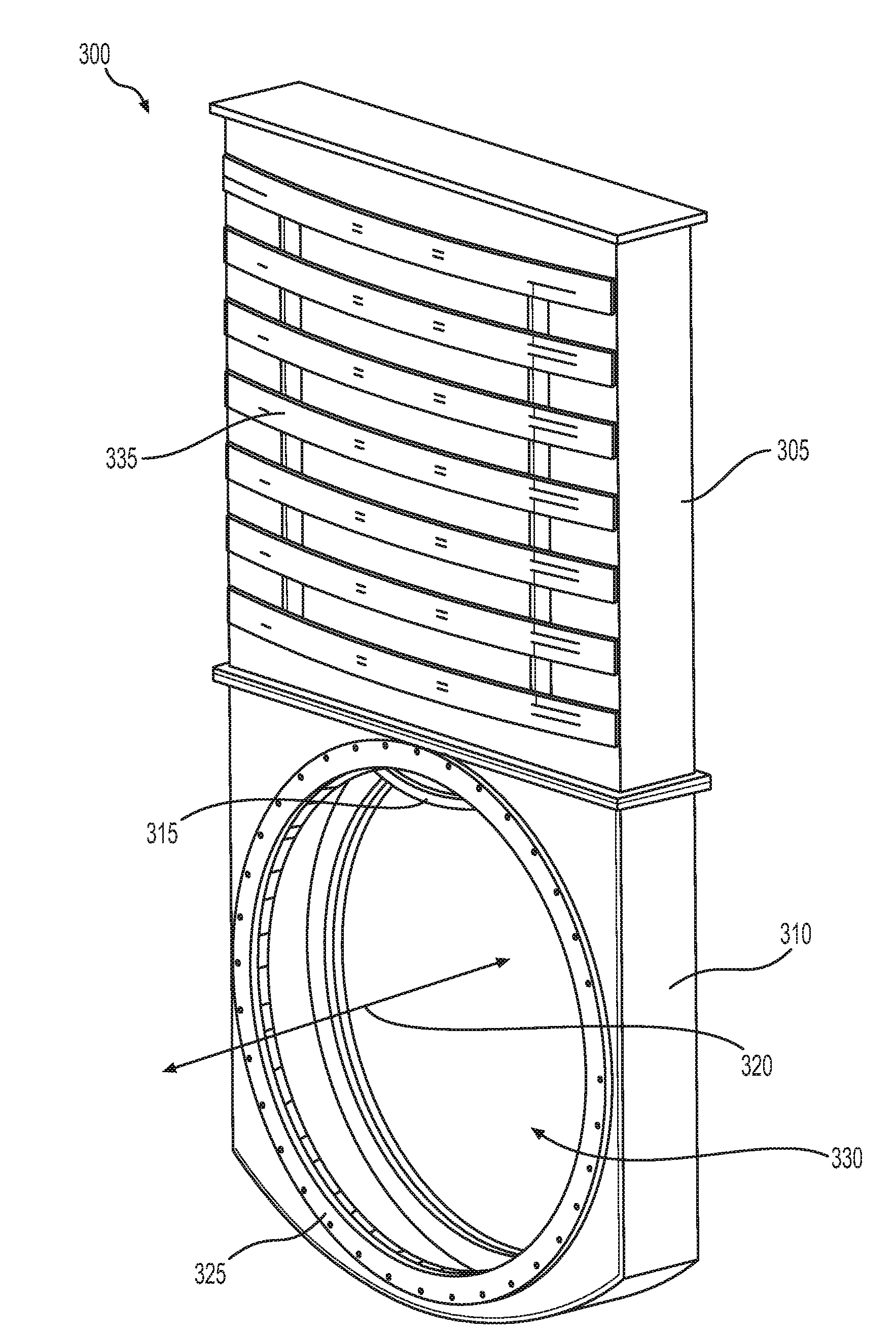
[0005]At least some embodiments of the present disclosure are directed to a gate valve operable to isolate sections of an externally pressurized, evacuated, or near vacuum tubular structure. In accordance with aspects of the disclosure, the valve, when open, will also accommodate a passing vehicle within the diameter of the tube.

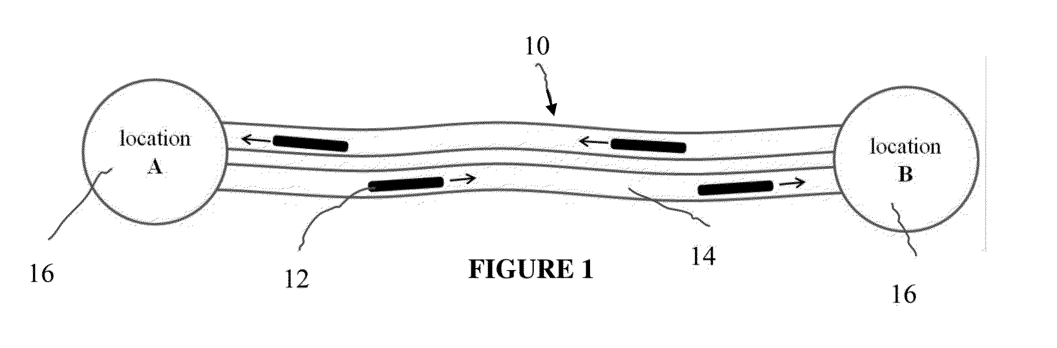
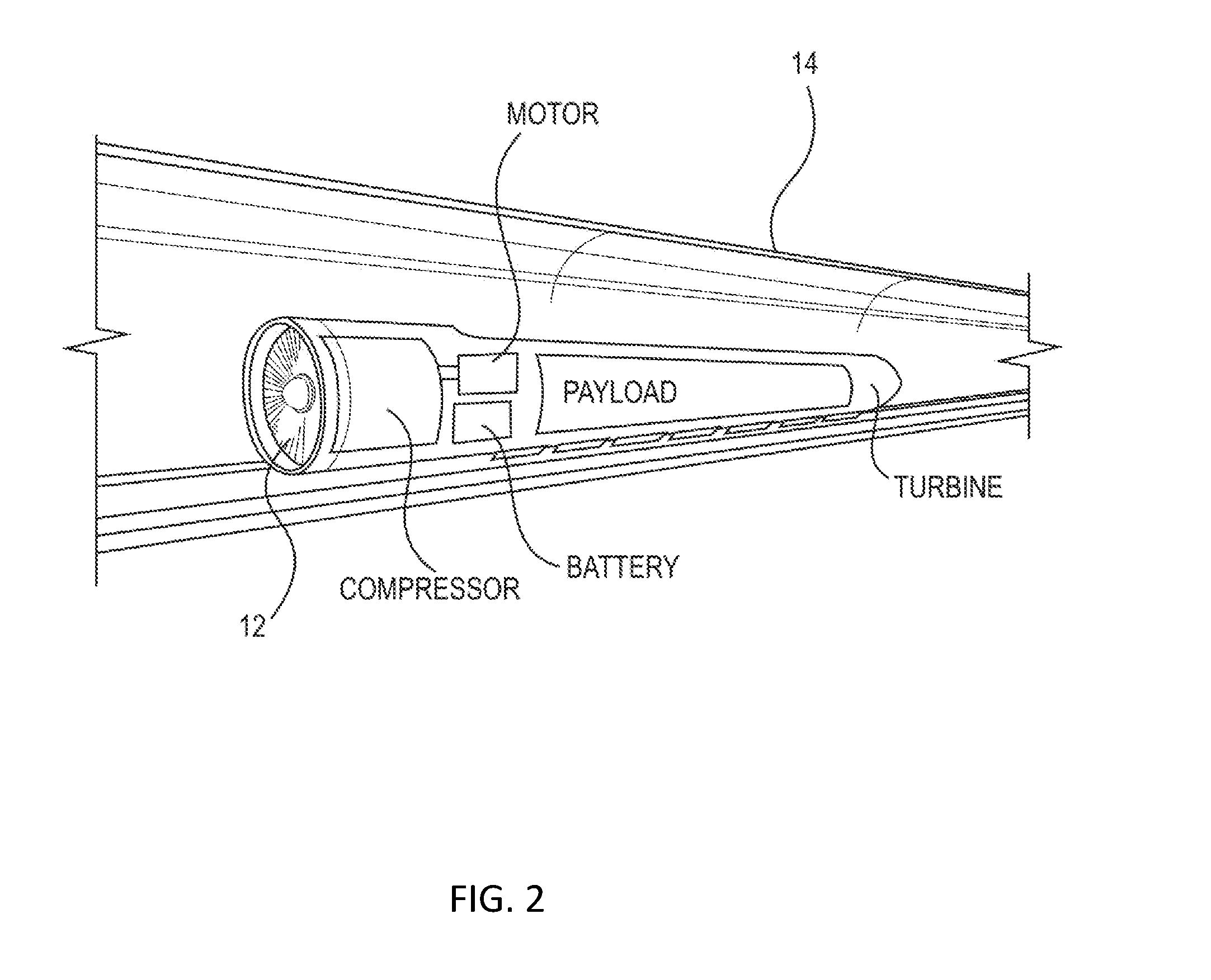
[0006]Aspects of the present disclosure are directed to a high-speed transportation system, the system comprising: at least one transportation tube having at least one track along a transportation path; a plurality of capsules configured for travel through the at least one tube between stations; a propulsion system adapted to propel the at least one capsule through the tube; a levitation system adapted to levitate the capsule within the tube; and at least one tube sealer arranged along the at least one tube and configured to selectively create an airlock in the at least one tube.

[0007]In certain embodiments, the at least one tube sealer comprises a gate valv...


PUM


Abstract

A high-speed transportation system, the system including at least one transportation tube having at least one track, at least one capsule configured for travel through the at least one tube between stations, a propulsion system adapted to propel the at least one capsule through the tube; a levitation system adapted to levitate the capsule within the tube, and at least one tube sealer arranged along the at least one tube and configured to create an airlock in the at least one tube. In embodiments, the tube sealer may include a gate valve and/or an airbag.

Description

CROSS REFERENCE TO RELATED APPLICATIONS[0001]The present application claims the benefit of U.S. Provisional Application No. 62 / 113,511 filed on Feb. 8, 2015, U.S. Provisional Application No. 62 / 232,876 filed on Sep. 25, 2015, and U.S. Provisional Application No. 62 / 242,562 filed on Oct. 16, 2015, the disclosures of which are expressly incorporated by reference herein in their entireties.FIELD OF THE DISCLOSURE[0002]The present disclosure relates to gate valves and air lock systems (e.g., using gate valves) for a high-speed transportation system, and methods of use thereof.BACKGROUND OF THE DISCLOSURE[0003]A high speed, high efficiency transportation system utilizes a low-pressure environment in order to reduce drag on a vehicle at high operating speeds, thus providing the dual benefit of allowing greater speed potential and lowering the energy costs associated with overcoming drag forces. In embodiments, these systems may use a near vacuum (e.g., low-pressure) environment within a t...

Claims


Application Information

Patent Timeline
Patent Type & Authority Applications(United States)
IPC IPC(8): F16K3/30F16K3/12F16K3/03B61B13/10
CPCB61B13/10F16K3/30F16K3/12F16K3/03F16K1/2014F16K3/02F16K3/06F16K7/10F16K27/044B61C11/06B61B13/08F16K3/04
Inventor COTHERN, KYLEGAUNT, MICHAELRONACHER, THOMASSHAFRIR, DANIELBAMBROGAN, BROGANGIEGEL, JOSHUA
Owner HYPERLOOP TECH INC
Why Eureka
Try Eureka