Auto-calibration of automatic grade control system in a working machine

a grade control system and working machine technology, applied in altitude or depth control, construction, roads, etc., can solve the problems of time-consuming and time-consuming to calibrate the conventional system, application of insufficient quantities of paving material in the rutted, potholed or otherwise damaged areas, and repeated rutting or other wear damage in the new pavement in relatively short order

Active Publication Date: 2016-08-11
ROADTEC
View PDF2 Cites 9 Cited by
  • Summary
  • Abstract
  • Description
  • Claims
  • Application Information

AI Technical Summary

Benefits of technology

[0010]Among the advantages of a preferred embodiment of the invention is that it provides a system for automatically calibrating the grade and slope control systems for a working machine. Additional objects and advantages of this invention will become apparent from an examination of the drawings and the ensuing description.
[0011]The use of the terms “a”, “an”, “the” and similar terms in the context of describing the invention are to be construed to cover both the singular and the plural, unless otherwise indicated herein or clearly contradicted by context. The terms “comprising”, “having”, “including” and “containing” are to be construed as open-ended terms (i.e., meaning “including, but not limited to,”) unless otherwise noted. The terms “substantially”, “generally” and other words of degree are relative modifiers intended to indicate permissible variation from the characteristic so modified. The use of such terms in describing a physical or functional characteristic of the invention is not intended to limit such characteristic to the absolute value which the term modifies, but rather to provide an approximation of the value of such physical or functional characteristic. All methods described herein can be performed in any suitable order unless otherwise specified herein or clearly indicated by context.
[0012]The use of any and all examples or exemplary language (e.g., “such as” and “preferably”) herein is intended merely to better illuminate the invention and the preferred embodiments thereof, and not to place a limitation on the scope of the invention. Nothing in the specification should be construed as indicating any element as essential to the practice of the invention unless so stated with specificity. Several terms are specifically defined herein. These terms are to be given their broadest possible construction consistent with such definitions, as follows:
[0013]The terms “above”, “upper” and similar terms, when used with respect to a working machine or a component of a working machine, refer to a relative location or direction away from the surface on which the machine is operated.
[0014]The terms “below”, “lower” and similar terms, when used with respect to a working machine or a component of a working machine, refer to a relative location or direction towards the surface on which the machine is being operated.
[0015]The terms “front”, “forward” and similar terms, when used with respect to a working machine or a component of a working machine, refer to a relative location or direction towards the leading end of the working machine as it travels during operation.

Problems solved by technology

Without prior surface treatment, however, this method of repair generally results in the application of insufficient quantities of paving material in the rutted, potholed or otherwise damaged areas, because the overlay will be applied at the same rate per unit of roadway width in damaged areas (which have a greater depth across the width) as in the undamaged areas.
The resulting reduced density in the overlay of the previously damaged areas will lead to renewed rutting or other wear damage in the new pavement in relatively short order.
This can require the raising of road shoulders, guardrails and manhole covers and the adjustment of overpass clearances, all of which is unnecessary if a proper milling technique is employed.
However, it is a time-consuming matter to calibrate the conventional systems for grade and slope control in the conventional manner prior to beginning a milling or paving operation.
Furthermore, conventional calibration techniques for attitude control systems require significant operator training.

Method used


Image

  • Auto-calibration of automatic grade control system in a working machine
  • Auto-calibration of automatic grade control system in a working machine
  • Auto-calibration of automatic grade control system in a working machine

Examples


Embodiment Construction

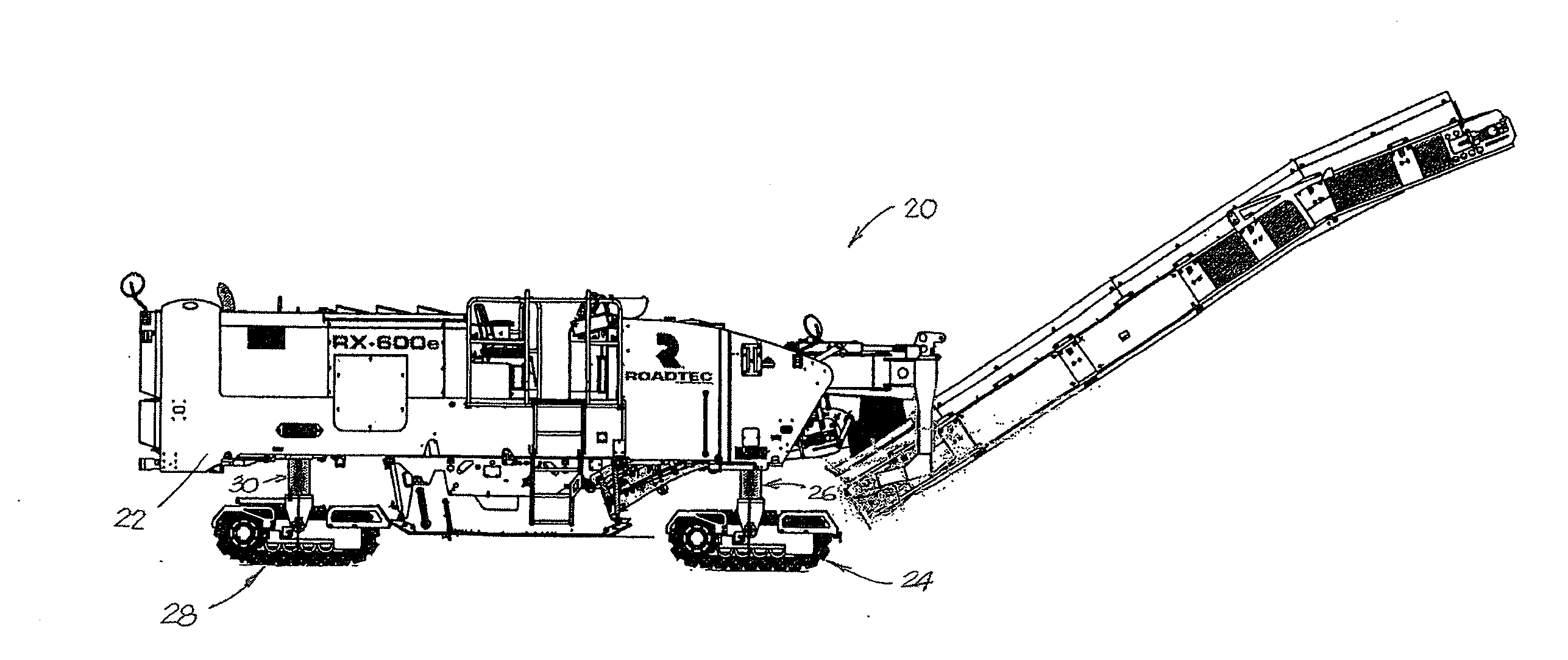
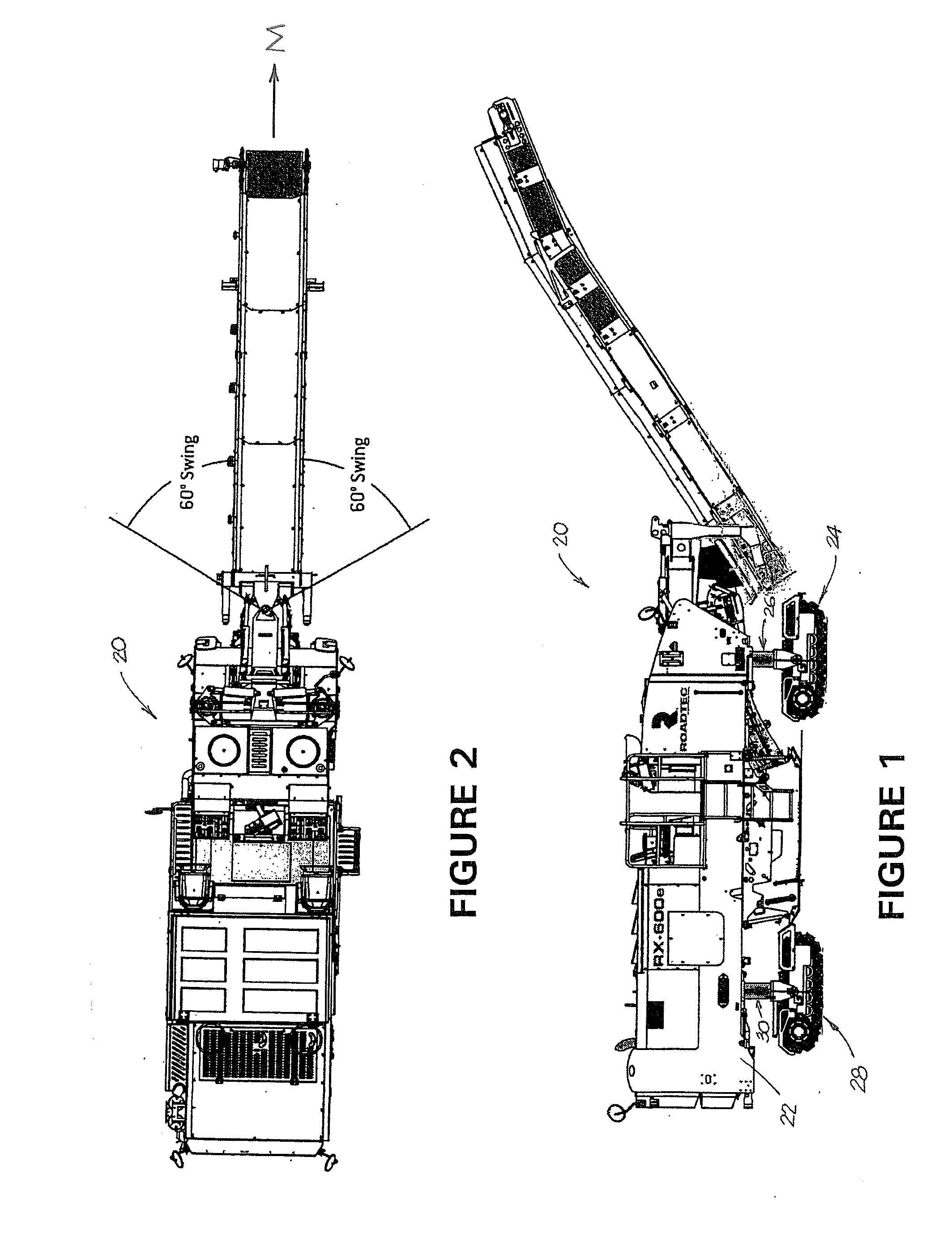
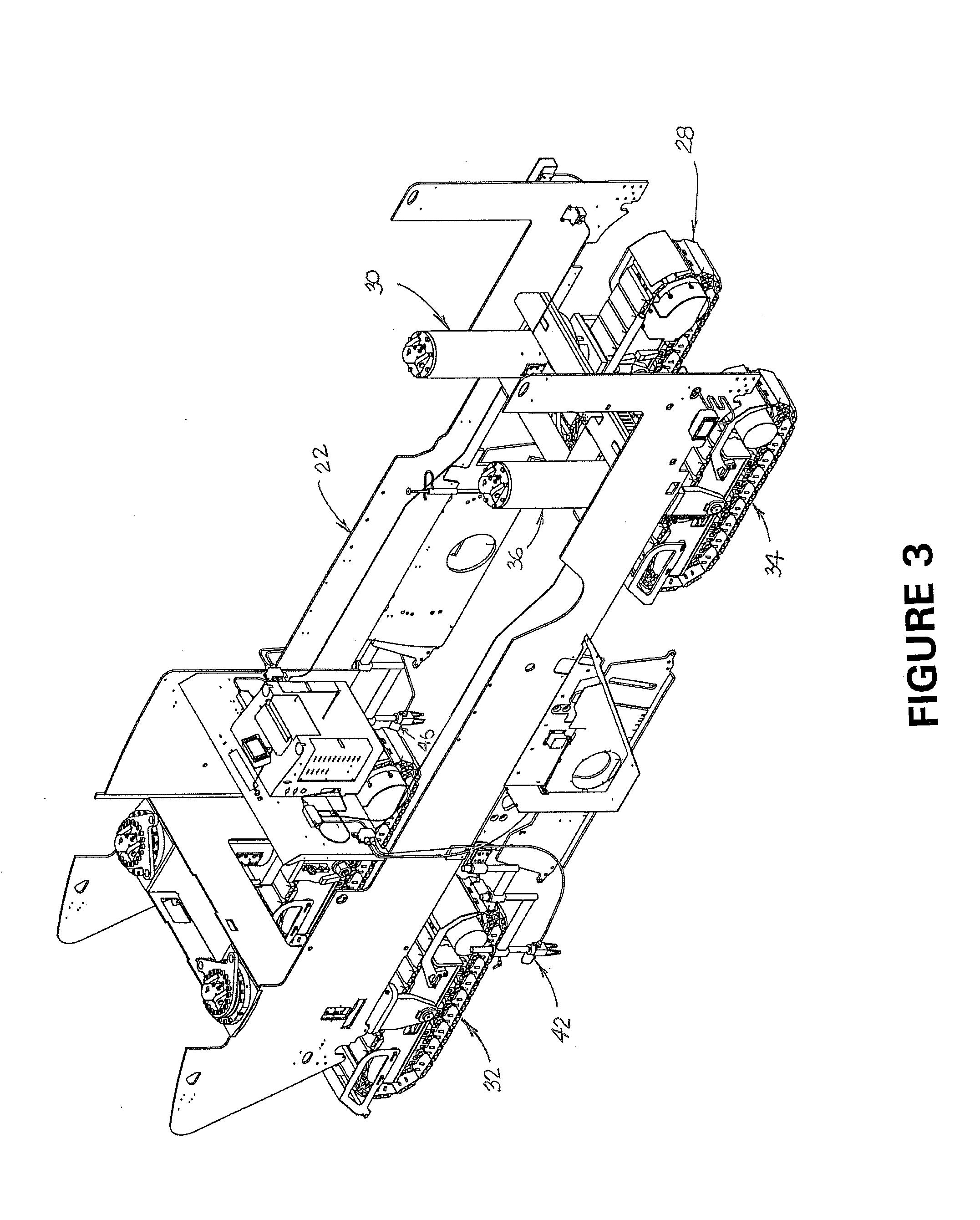
[0035]As shown in FIGS. 1-4, a milling machine that may be equipped with a preferred embodiment of the present invention is indicated generally at 20. This machine comprises a mobile vehicle having a frame 22 and a plurality of ground-engaging drive assemblies, including right front track assembly 24, which is mounted on column 26, right rear track assembly 28, which is mounted on column 30, left front track assembly 32, which is mounted on a column (not shown, but substantially similar to columns 26, 30 and 36) and left rear track assembly 34, which is mounted on column 36. As is conventional, linear actuators within the columns (not shown) are adapted to raise and lower the frame of the milling machine with respect to the surface being milled Preferably, the front drive assemblies are steerable to provide precise directional control. The drive assemblies of machine 20 are driven by a machine drive system including conventional hydraulic motors (not shown) and an engine (also not s...


PUM


Abstract

A working machine such as a road milling machine of an asphalt paving machine has an automatic grade and slope control system that causes the machine to maintain a pre-selected grade and slope with respect to a reference without significant operator input. A calibration system employs a calibration controller to calibrate the automatic grade and slope control system. The calibration controller causes a current to be sent to a valve that operates a linear actuator that may be employed to change the attitude of the frame of the working machine. The calibration controller uses feedback from at least one sensor, such as a height-measuring sensor or a slope-measuring sensor, in an iterative process that determines the minimum current necessary to cause a change in the attitude of the frame of the working machine. Once this minimum value is determined, the system will establish the optimum settings for the automatic grade and slope control system to improve its efficiency and cause it to operate more smoothly.

Description

CROSS-REFERENCE TO RELATED APPLICATION[0001]This application claims the benefit of U.S. Provisional Patent Application No. 62 / 114,656, which was filed on Feb. 11, 2015.FIELD OF THE INVENTION[0002]This invention relates to a system and method for automatically calibrating an automatic grade control system for a working machine such as a milling machine or an asphalt paving machine. More specifically, the invention comprises a system and method for automatically determining the minimum current necessary to cause a change in the transverse and / or longitudinal attitude of a working machine.BACKGROUND AND DESCRIPTION OF THE PRIOR ART[0003]Roadwork is typically carried out by working machines that carry a working implement and travel along a roadway. In the operation of road milling machines and paving machines, it is critical to control the transverse slope and / or the longitudinal grade of the working implement with respect to the roadway. Consequently, conventional road working machines...

Claims


Application Information

Patent Timeline
Patent Type & Authority Applications(United States)
IPC IPC(8): G05D1/04E01C23/08
CPCE01C23/08G05D1/04E02F9/2025E02F9/2041E02F9/264E02F9/265
Inventor PAYNE, BYRONENSELL, JEFFERY A.
Owner ROADTEC
Why Eureka
Try Eureka