Optical ring network

a technology of optical rings and optical rings, applied in the field of optical rings, can solve the problems of too expensive equipment and expensive networks to ensure signal detection, and achieve the effect of fast transmission

Inactive Publication Date: 2016-08-11
ALCATEL LUCENT SAS
View PDF26 Cites 0 Cited by
  • Summary
  • Abstract
  • Description
  • Claims
  • Application Information

AI Technical Summary

Benefits of technology

The technical effect of this patent is to provide a solution for fast transmission of signals within a limited area without requiring expensive equipment like fast tunable receivers.

Problems solved by technology

However, such networks require expensive equipment to ensure signal detection.
Thus, for some applications such as the communication between neighboring base stations of a cellular network, such equipments are too expensive and provide a higher quality than required due to the limited distance between the different base stations.

Method used


Image

  • Optical ring network
  • Optical ring network
  • Optical ring network

Examples


Embodiment Construction

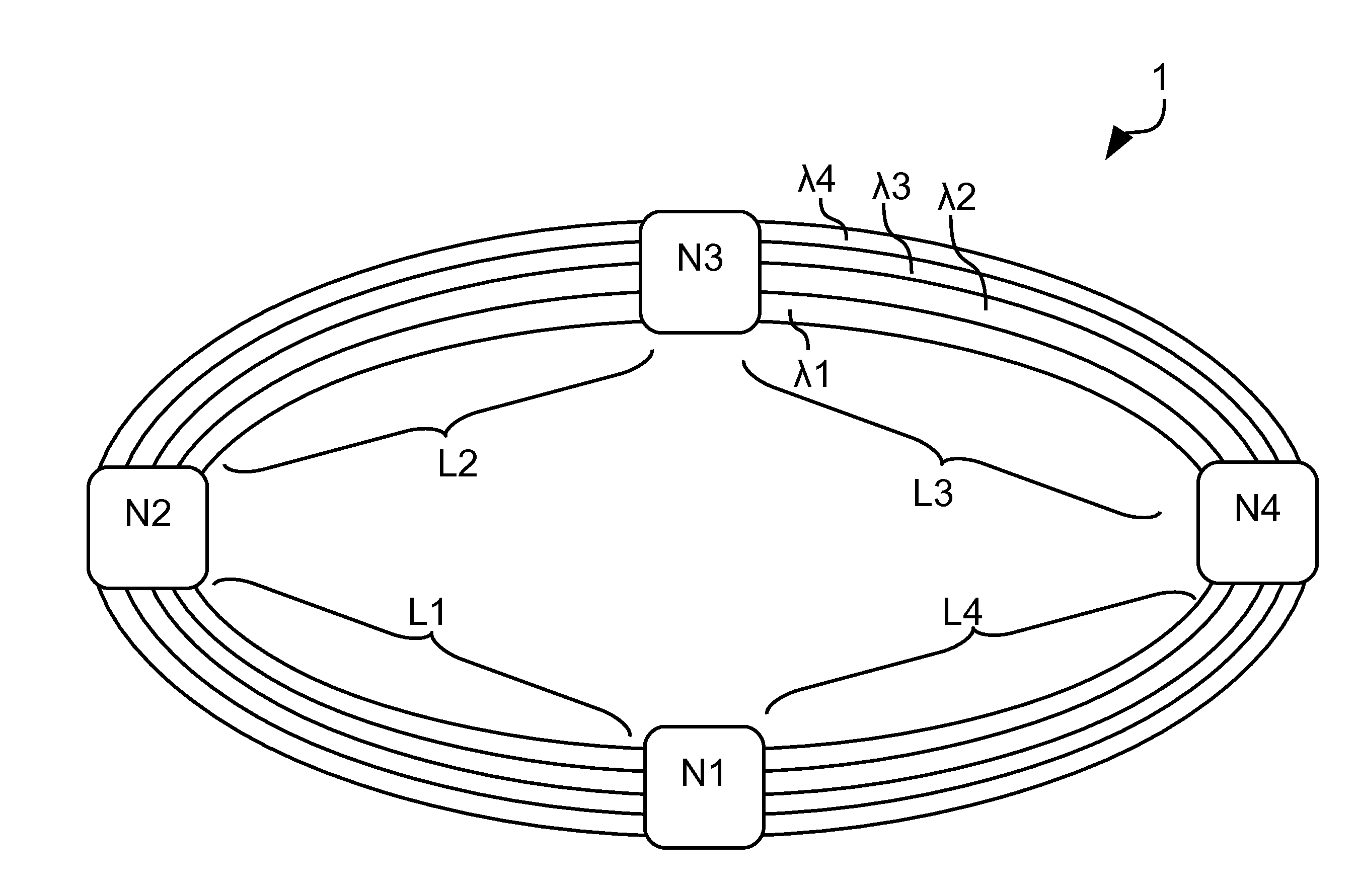
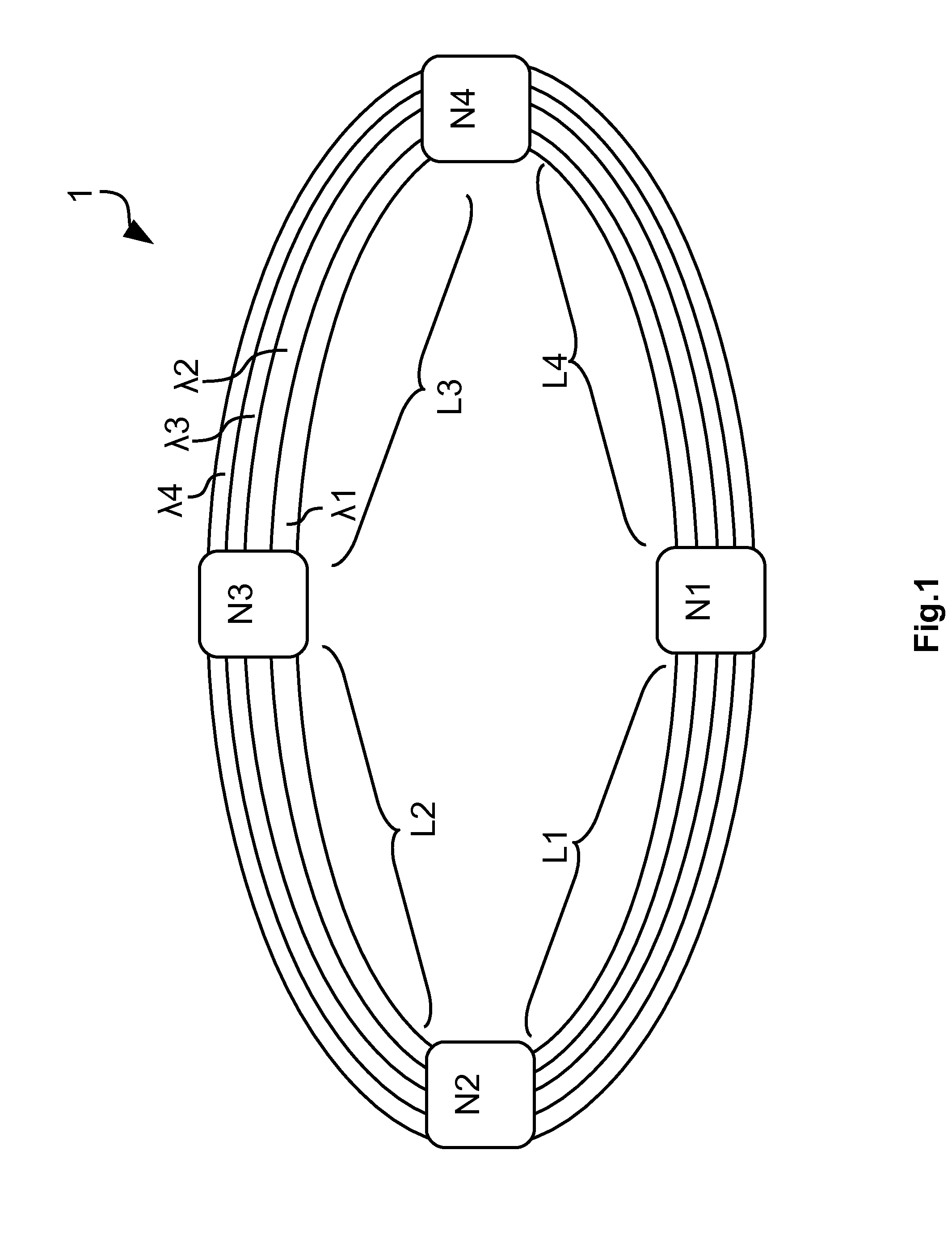
[0031]The embodiments of the present invention refer to an optical ring network 1 comprising a plurality of nodes, four in the present example noted Ni with i=1 . . . 4, as represented in FIG. 1. The nodes Ni are linked by optical links noted Lj with j=1 . . . 4 such as optical fibers, for example single mode fibers. The optical ring network 1 is configured for transmitting a plurality of wavelength channels λ, the number of wavelength channels being equal or larger than the number of nodes Ni. In the present example, four wavelength channels noted λ1, λ2, λ3 and λ4 that are multiplexed according to a wavelength division multiplexing (WDM) technique to be transmitted through the optical ring network 1. It has to be noted that the different wavelengths are represented schematically by different lanes in the link, however all the wavelength channels are multiplexed in a single optical fiber corresponding to a link Lj. One wavelength channel λk with k=1 . . . 4 is dedicated to signals ...


PUM


Abstract

An exemplary apparatus is provided for an optical node of an optical ring network. The optical node comprises a main branch with a wavelength blocker configured to block at least one wavelength of signals targeted to a particular node and to permit the signals received on the other wavelength channels pass, a reception unit tuned to the at least one wavelength dedicated to signals targeted to the particular node, a first optical coupler configured to transmit the signals received from a previous node of the optical ring network both to the main branch and to the reception unit, a transmission unit configured to transmit signals to a wavelength channel according to their targeted node, and a second optical coupler configured to receive the signals received from the main branch and from the transmission unit and to transmit the received signals toward a next node of the optical ring network.

Description

BACKGROUND OF THE INVENTION[0001]The present invention relates to the field of telecommunication networks and more specifically to fast transmission enabling a fast transmission of data within a limited area and for a limited cost.[0002]Optical fibers enable fast transmissions with large throughput thanks to the wavelength multiplexing. However, such networks require expensive equipment to ensure signal detection. Such equipments are fast tunable receivers based on coherent detection. Thus, for some applications such as the communication between neighboring base stations of a cellular network, such equipments are too expensive and provide a higher quality than required due to the limited distance between the different base stations.SUMMARY OF THE INVENTION[0003]It is therefore an object of the present invention to overcome the above mentioned drawbacks of the state of the art and to provide a solution that enables fast transmission within a limited area without requiring expensive e...

Claims


Application Information

Patent Timeline
Patent Type & Authority Applications(United States)
IPC IPC(8): H04J14/02H04B10/275
CPCH04J14/0204H04J14/0205H04B10/275H04J14/021H04J14/0283H04J14/0206H04Q11/00H04B10/25H04B10/40H04B10/50H04B10/60
Inventor DE VALICOURT, GUILHEMPOINTURIER, YVAN
Owner ALCATEL LUCENT SAS
Why Eureka
Try Eureka