Microphone

a technology of microphones and microphones, applied in the field of microphones, can solve the problems of not being able to examine the structure of microphones against water, rubbish, or dust ingress, and the environmental resistance of microphones, so as to prevent the breakdown of an acoustic transducer, prevent water, rubbish, or dust ingress, and achieve high environmental resistance

Active Publication Date: 2016-08-11
PANASONIC INTELLECTUAL PROPERTY MANAGEMENT CO LTD
View PDF10 Cites 35 Cited by
  • Summary
  • Abstract
  • Description
  • Claims
  • Application Information

AI Technical Summary

Benefits of technology

[0079]In the foregoing configuration, even when a kitchen device is washed with high-pressure water using a high-pressure washer, it is possible to provide the kitchen device in which the microphone or the microphone unit is not damaged.
[0080]According to the embodiments, it is possible to provide the microphone which can prevent breakdown of an acoustic transducer, and can be installed outside a...

Problems solved by technology

In the technologies of the related art, however, there is a problem in that the structures of microphones against ingress of water, rubbish, or dust have not be examined when the mic...

Method used


Image

  • Microphone
  • Microphone
  • Microphone

Examples


first embodiment

[0102]Hereinafter, a first embodiment of the invention will be described in detail with reference to FIGS. 1(a) to 2.

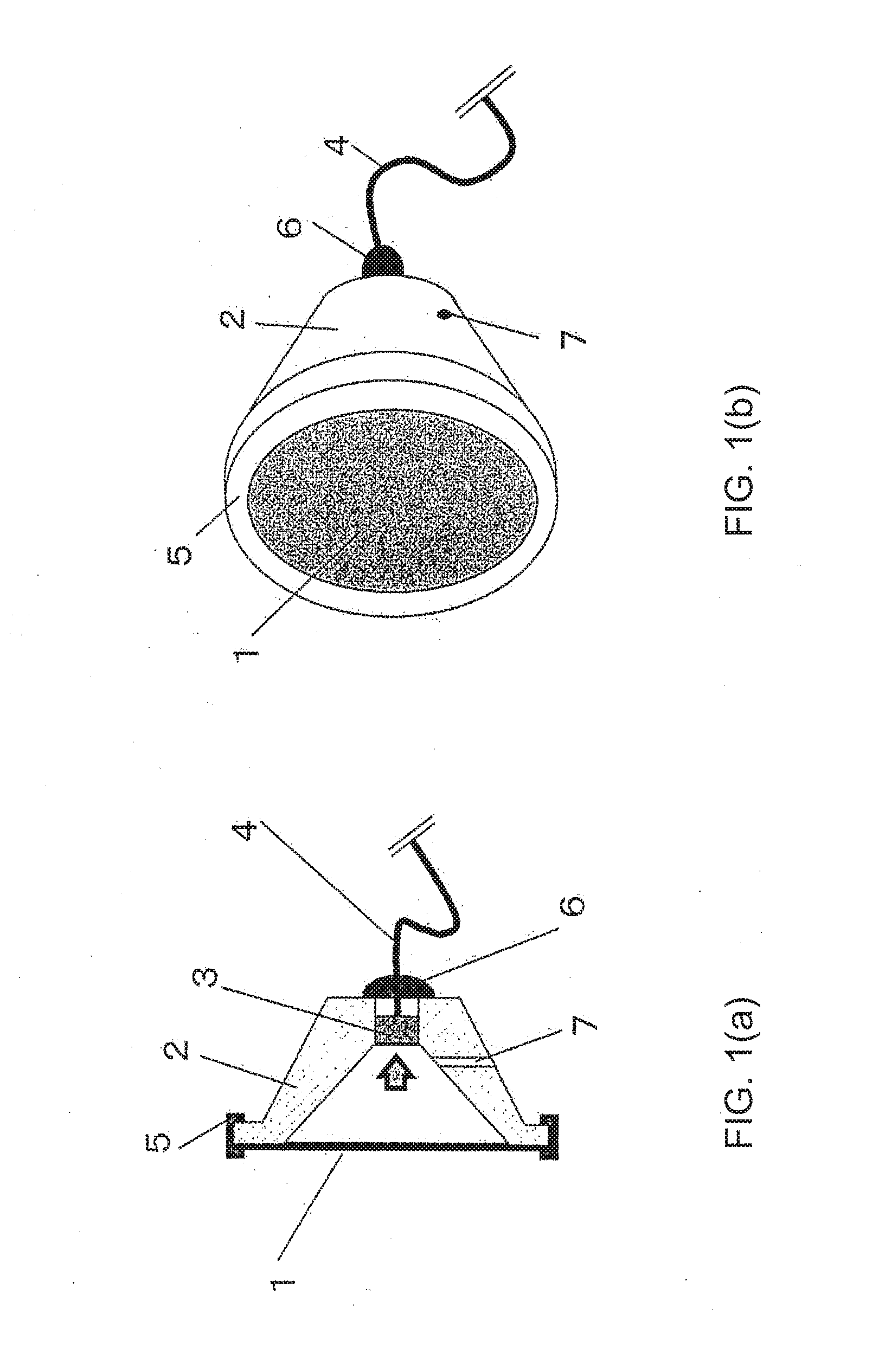
[0103]FIGS. 1(a) and 1(b) are schematic diagrams illustrating the structure of a microphone according to the first embodiment of the invention. FIG. 1(a) is a sectional view of the microphone and FIG. 1(b) is a perspective view of the microphone.

[0104]As illustrated in FIGS. 1(a) and 1(b), the microphone according to the embodiment is configured to include a diaphragm 1, a frame 2, an acoustic transducer 3, a wire 4 that transmits a signal of the acoustic transducer 3 to the outside or supplies power to the acoustic transducer 3, and a packing 5 that prevents ingress of water, rubbish, or dust from a connection portion of the diaphragm 1 and the frame 2, and a resin coating member 6 that prevents ingress of water, rubbish, or dust from a gap between the frame 2 and the wire 4.

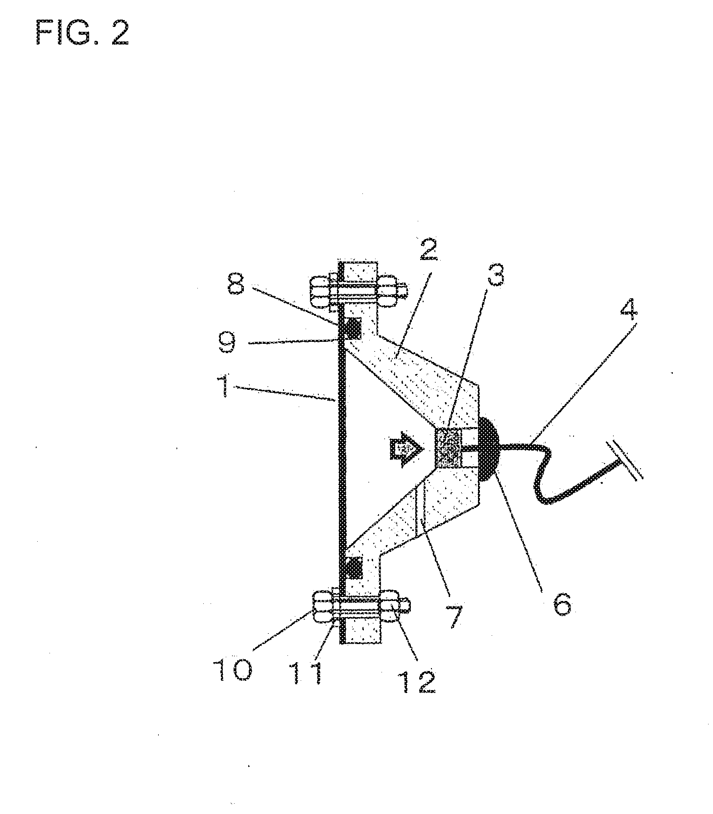
[0105]In FIG. 1(a), the internal shape of the frame 2 is the shape of a conical surface, but ...

second embodiment

[0114]Hereinafter, a second embodiment of the invention will be described in detail with reference to FIG. 4.

[0115]FIG. 4 is a schematic sectional view illustrating the structure of a microphone according to the second embodiment of the invention. As illustrated in FIG. 4, the microphone according to the embodiment is different from the microphone in FIG. 1(a) according to the first embodiment in the internal shape of a frame 13, a disposal position and a sound input direction (indicated by an arrow in FIG. 4) of the acoustic transducer 3.

[0116]In the embodiment, the internal shape of the frame 13 is the surface of a parabolic surface used for a parabolic antenna. This is because a sound to be input is indicated by the arrow in FIG. 4 in the acoustic transducer 3. By collecting the sound in the shape of the parabolic surface, it is possible to realize a telephoto microphone capable of collecting a more distant sound than the shape of the microphone described in the first embodiment....

third embodiment

[0117]Hereinafter, a third embodiment of the invention will be described in detail with reference to FIGS. 5(a), 5(b), and 6.

[0118]The embodiment is different from the first and second embodiments in that a plurality of acoustic transducers are present.

[0119]FIGS. 5(a) and 5(b) are schematic diagrams illustrating the structure of a microphone according to the third embodiment of the invention. FIG. 5(a) is a plan view illustrating the microphone from which a diaphragm 107 and a packing 113 are excluded. FIG. 5(b) is a sectional view illustrating the microphone.

[0120]As illustrated in FIGS. 5(a) and 5(b), the microphone according to the embodiment is configured to include the diaphragm 107, a frame 108 having a partition wall 109, two acoustic transducers 110a and 110b, wires 112a and 112b that transmit signals of the acoustic transducers to the outside or supply power to the acoustic transducers, the packing 113 that prevents ingress of water, rubbish, or dust from a connection port...


PUM


Abstract

A microphone structure has a diaphragm; a frame of which an inside is processed in a shape of a semispherical surface, a parabolic surface, or a conical surface; an acoustic transducer that converts sound pressure into an electric signal; and a wire that transmits the electric signal from the acoustic transducer to outside. A sound pressure input surface of the acoustic transducer is disposed on a bottom surface portion of the semispherical surface, the parabolic surface, or the conical surface inside the frame. The diaphragm and the frame, and the frame and the wire include waterproof mechanisms preventing ingress of water.

Description

CROSS REFERENCE TO RELATED APPLICATIONS[0001]This application is a continuation of PCT application No. PCT / JP14 / 005218, which was filed on Oct. 15, 2014 based on Japanese Patent Application (No. P2013-214563) filed on Oct. 15, 2013 and Japanese Patent Application (No. P2014-002658) filed on Jan. 9, 2014, the contents of which are incorporated herein by reference.BACKGROUND OF THE INVENTION[0002]1. Field of the Invention[0003]One or more embodiments of the present invention relate to a microphone disposed outside or inside a vehicle cabin, and particularly, to the structure of a waterproof microphone configured to prevent ingress of water or rubbish.[0004]2. Description of the Related Art[0005]As an use of a microphone installed outside a vehicle cabin, for example, PTL 1 discloses an example of a device in which a plurality of microphones are disposed outside a vehicle cabin to detect a travelling sound of another vehicle and a sound source direction of the another vehicle is estima...

Claims


Application Information

Patent Timeline
IPC IPC(8): H04R1/44E05F15/70B60R16/037G10L17/24
CPCH04R1/021H04R1/44H04R1/406H04R1/46H04R3/005H04R19/005H04R2201/003H04R2201/403H04R2499/13B60R11/0247H04R1/04E05F15/70B60R16/0373G10L17/24G10L2015/223H04R1/086
Inventor OGURA, HIROSHIDOI, KAZUMOTOTAKESHI, FUTOSHI
Owner PANASONIC INTELLECTUAL PROPERTY MANAGEMENT CO LTD
Why Eureka
Try Eureka