
Optical film with pressure sensitive adhesive and image display device

a technology of pressure sensitive adhesives and optical films, applied in film/foil adhesives, instruments, polarising elements, etc., can solve the problems of reducing the visibility of screen images, and the outgas generated by heating remains as bubbles, so as to reduce the interface

Inactive Publication Date: 2016-08-18
NITTO DENKO CORP
View PDF0 Cites 21 Cited by
  • Summary
  • Abstract
  • Description
  • Claims
  • Application Information

AI Technical Summary

Benefits of technology

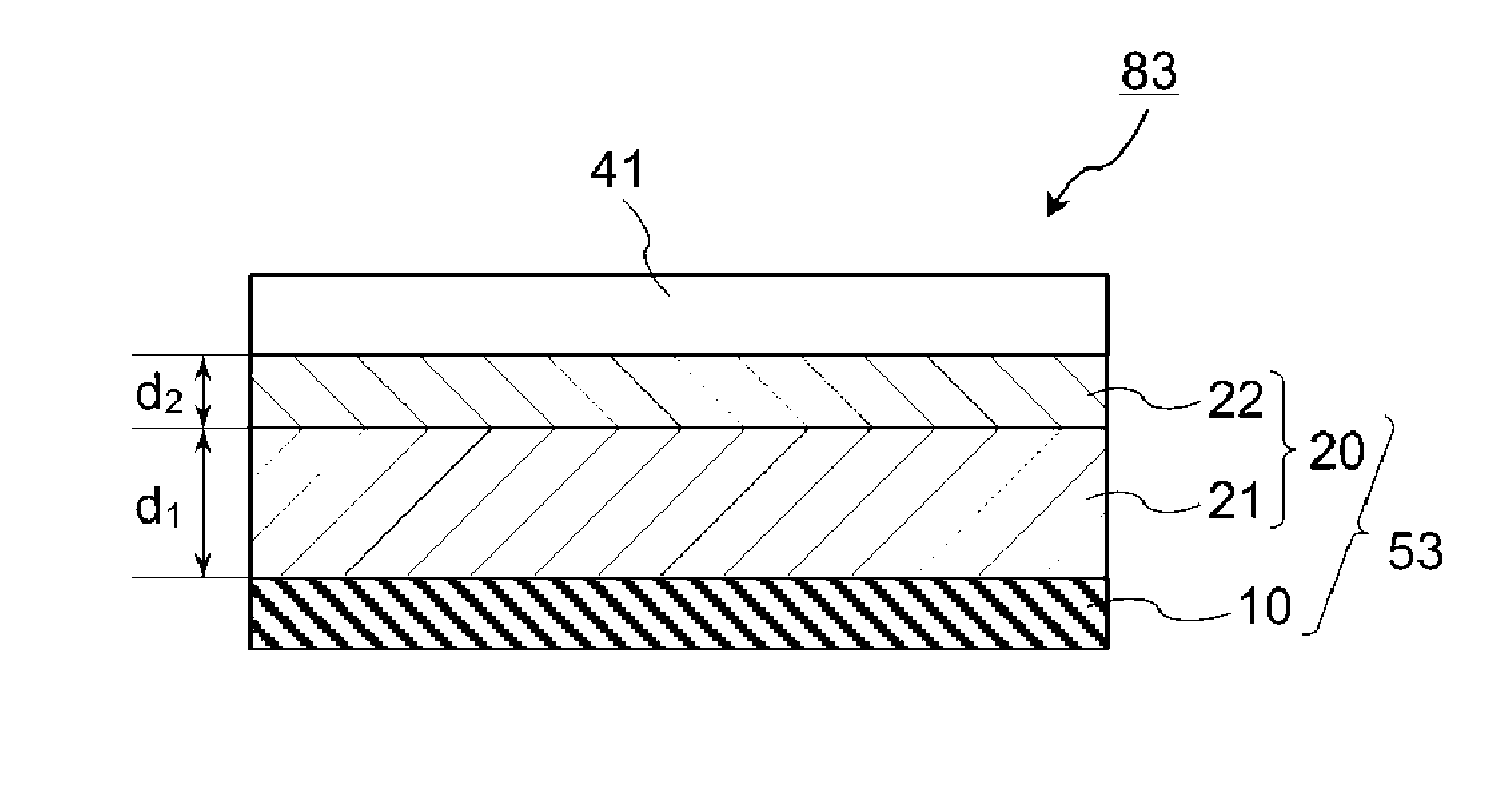
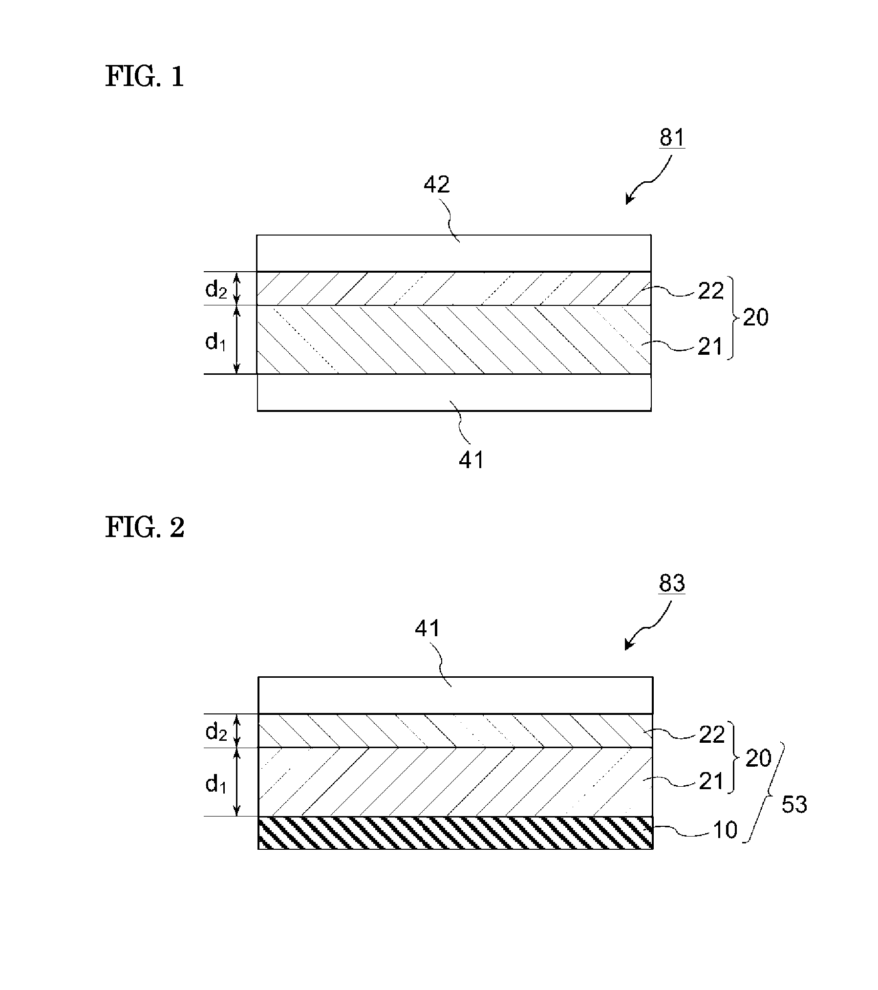
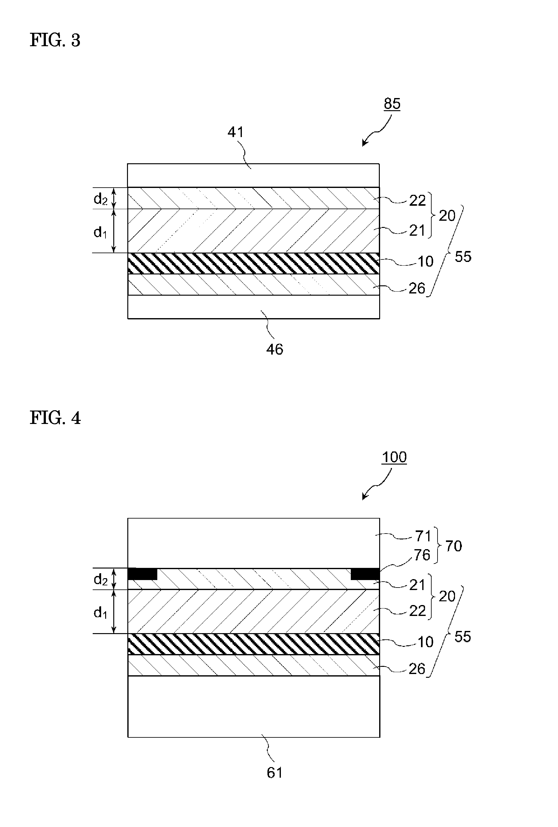
The present invention relates to a laminated pressure sensitive adhesive sheet used for bonding an image display panel and a front transparent member such as a transparent plate or a touch panel. The invention also includes an optical film with pressure sensitive adhesive. The technical effect of the invention is to suppress display unevenness by controlling the storage elastic modulus of each pressure sensitive adhesive layer in the laminated pressure sensitive adhesive sheet and the temperature dependency of the pressure sensitive adhesive layer provided on the optical film side. Additionally, the invention improves the adhesiveness of the pressure sensitive adhesive to the front transparent panel.

Problems solved by technology

When a sheet pressure sensitive adhesive is used as an interlayer filler, the pressure sensitive adhesive cannot sufficiently penetrate to the vicinity of a printing level difference, and thus bubbles may remain to reduce the visibility of the screen image.
In recent years, front transparent plates made of resin such as acrylic or polycarbonate have come into use in view of weight saving and flexibility, and thus the problem has become apparent that outgas generated by heating remains as bubbles at the interface between the front transparent plate and the pressure sensitive adhesive sheet.

Method used


Image

  • Optical film with pressure sensitive adhesive and image display device
  • Optical film with pressure sensitive adhesive and image display device
  • Optical film with pressure sensitive adhesive and image display device

Examples


example 1

[0202]As an optical film, a polarizing plate including a transparent protective film on each of both surfaces of a polarizer composed of a 25 μm-thick iodine dyed stretched polyvinyl alcohol film was used. The cell-side pressure sensitive adhesive sheet was bonded to one surface (cell-side surface) of the polarizing plate using a roll laminator. Thereafter, the pressure sensitive adhesive sheet A was bonded to the other surface (viewing-side surface) of the polarizing plate using a roll laminator. Further, the pressure sensitive adhesive sheet E was bonded onto the pressure sensitive adhesive sheet A using a roll laminator. In this way, a polarizing plate with pressure sensitive adhesive on both sides was obtained in which the cell-side pressure sensitive adhesive sheet was provided on one surface of the polarizing plate, a laminated pressure sensitive adhesive sheet of the pressure sensitive adhesive sheet A and the pressure sensitive adhesive sheet E was provided on the other surf...


PUM

PropertyMeasurementUnit
Temperatureaaaaaaaaaa
Percent by massaaaaaaaaaa

Abstract

The optical film with pressure sensitive adhesive comprises an optical film and a front-side pressure sensitive adhesive sheet. The front-side pressure sensitive adhesive sheet is a laminated pressure sensitive adhesive sheet and includes a first pressure sensitive adhesive layer disposed in contact with the optical film, and a second pressure sensitive adhesive layer disposed at the furthest from the optical film. The first pressure sensitive adhesive layer has a storage elastic modulus of 9×10³ Pa or less at 150° C., and a ratio G′20 / G′150 of 20 or more, where G′20 is a storage elastic modulus at 20° C. and G′150 is a storage elastic modulus at 150° C. The second pressure sensitive adhesive layer has a storage elastic modulus of 4×10⁵ Pa or less at 20° C., and a storage elastic modulus of 1×10⁴ Pa or more at 150° C.

Description

TECHNICAL FIELD[0001]The present invention relates to a pressure sensitive adhesive sheet and an optical film with pressure sensitive adhesive, which are suitably used for formation of an image display device including a transparent plate, a touch panel, or the like on the front surface of an image display panel. The present invention also relates to an image display device using the pressure sensitive adhesive sheet or the optical film with pressure sensitive adhesive.BACKGROUND ART[0002]Liquid crystal displays and organic EL displays are widely used as various kinds of image display devices of mobile phones, car navigation devices, personal computer monitors, televisions and so on. On a viewing-side outermost surface of an image display panel, a front transparent plate (also referred to as a “window layer” etc.) such as a transparent resin plate or a glass plate may be provided, for the purpose of, for example, preventing damage to the image display panel due to impact from the ou...

Claims


Application Information

Patent Timeline
IPC IPC(8): C09J7/02B32B27/26B32B27/30G02B5/30B32B27/08B32B7/022
CPCC09J7/0217G02B5/3025B32B27/08B32B27/30B32B27/26B32B2457/20C09J2433/00C09J2201/606C09J2201/36C09J2203/318C09J133/08C09J7/385C09J7/255B32B7/10B32B33/00G02B5/30G02F1/133528C09J2483/005C09J2203/326B32B7/022B32B7/06B32B7/12B32B27/308B32B27/32B32B27/36C09D123/06B32B2250/24B32B2255/10B32B2255/26B32B2270/00B32B2307/4026B32B2307/42B32B2307/51B32B2307/514B32B2307/7145B32B2307/732B32B2307/748B32B2457/00B32B2457/208B32B2551/00C09J2301/208
Inventor TAKARADA, SHOUMIZUTANI, MASAKIYASUI, ATSUSHIYAMAMOTO, SHINYA
Owner NITTO DENKO CORP
Learn More