Torque converter having a reactor controlled by a jaw clutch

Active Publication Date: 2016-08-18
CHEN ZHONGTAI
View PDF34 Cites 7 Cited by
  • Summary
  • Abstract
  • Description
  • Claims
  • Application Information

AI Technical Summary

Benefits of technology

[0028]In the current prior art torque converter, reactor blade cross section geometries are often of airfoil shape, to optimize torque converter coupling point behavior. After idling and vehicle launch and during gear changes, the present invention allows the reactor to free spin during bypass disengage and re-engage. With such

Problems solved by technology

Unlike automatic transmissions, the prior art for torque converters has been stagnant, only slowly and incrementally advancing.
A number of criticisms exist for the prior art of torque converters.
Generally speaking, they are not shift-optimized, they require painful trade-offs between efficiency and performance, they are relatively large, they are relatively costly, and they are relatively complex.
The reactor/stator one-way clutch is overly complex, and relatively costly.
Although Fukunaga '709 replaces the one-wa

Method used


Image

  • Torque converter having a reactor controlled by a jaw clutch
  • Torque converter having a reactor controlled by a jaw clutch
  • Torque converter having a reactor controlled by a jaw clutch

Examples


Embodiment Construction

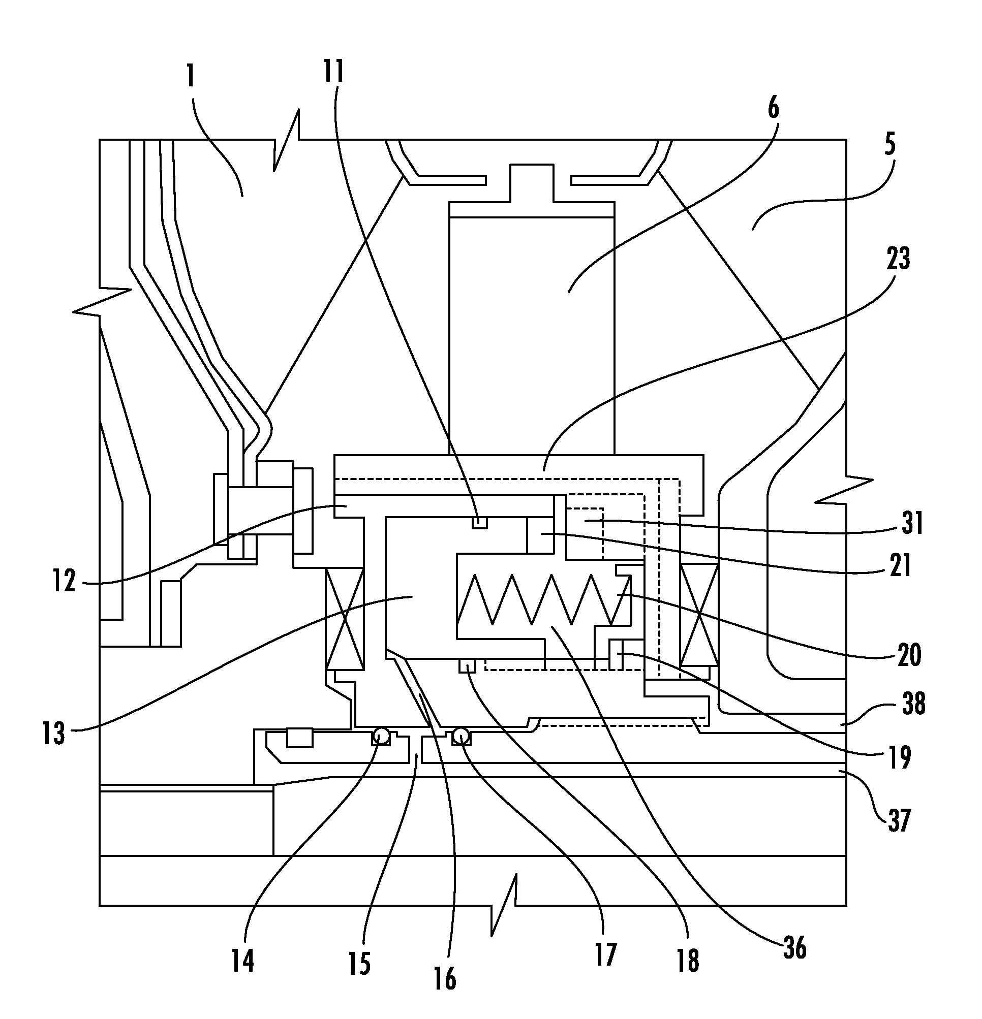
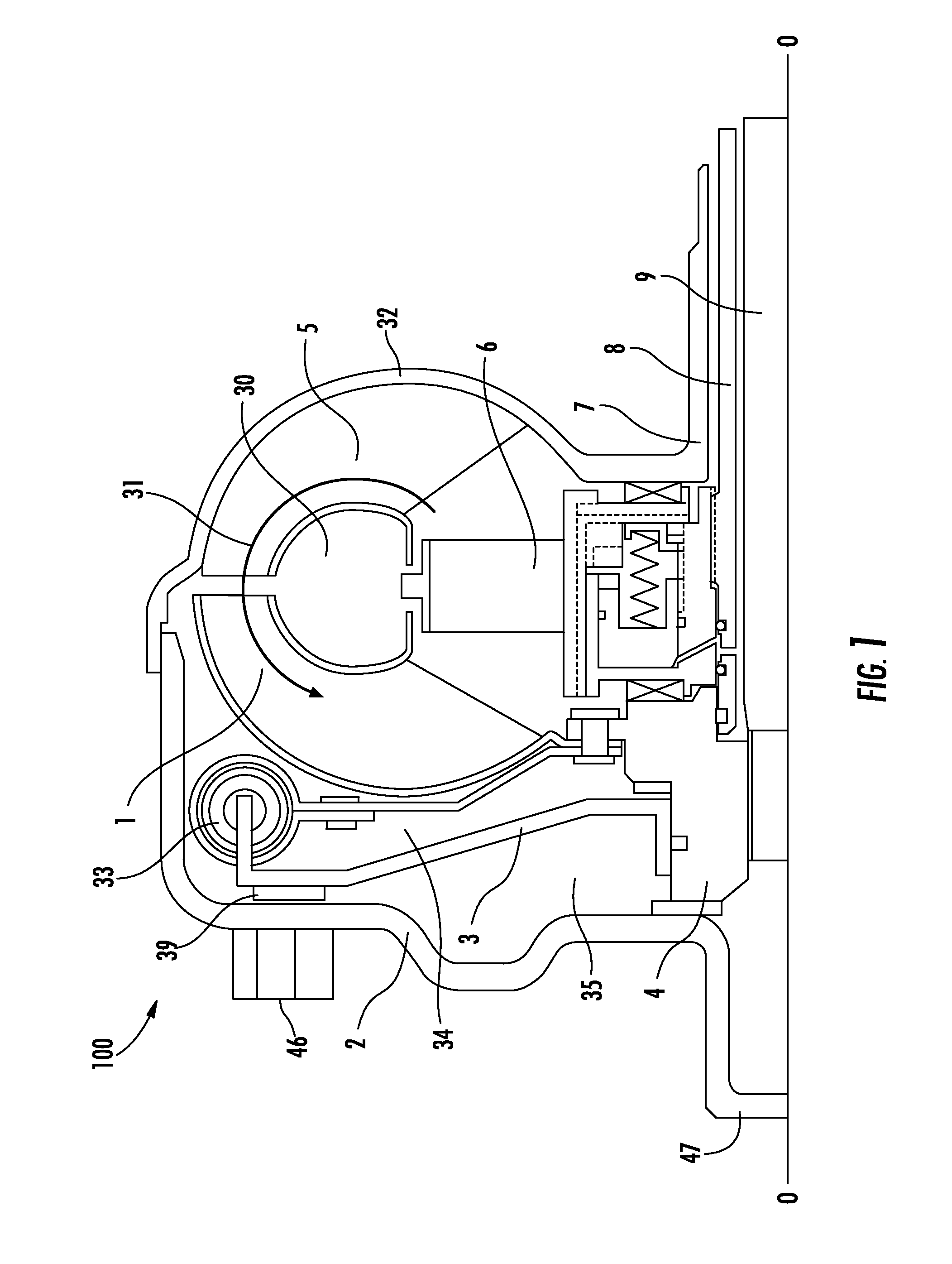
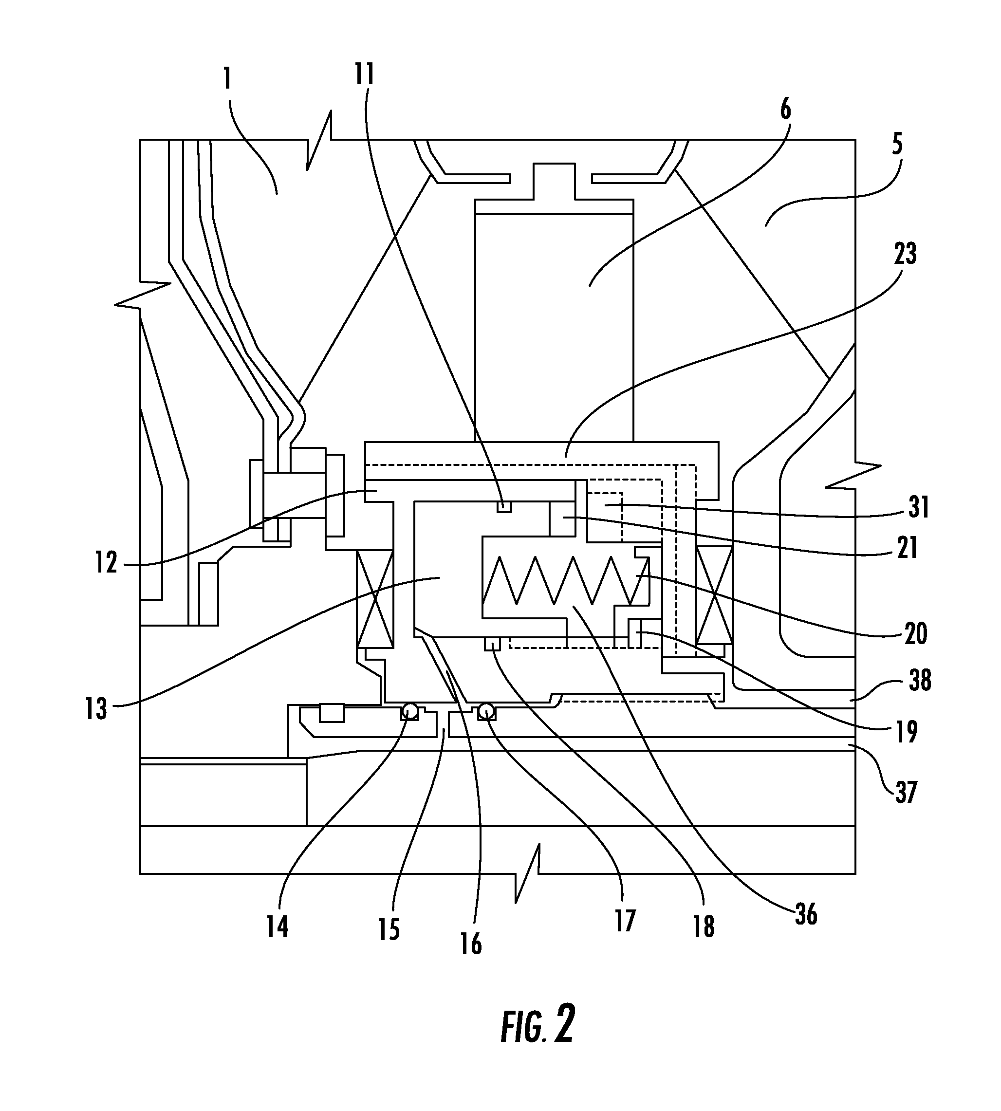
[0032]The following descriptions are not meant to limit the invention, but rather to add to the Summary of Invention, and illustrate the general design and implementation of a reactor jaw clutch in a torque converter. FIG. 1 shows a cross-sectional view of the present-invention torque converter 100. The torque converter 100 contains cover assembly 2 and a torus chamber 30, a turbine assembly 1, an impeller assembly 5, and a reactor 6. The torque converter 100 is filled with hydraulic fluid 31. The torque converter 100 has a bypass clutch 3 to lock the turbine assembly 1 to the cover 2.

[0033]The torque converter 100 rotates around an axis 0-0. The engine flywheel (not shown) is bolted to the nuts 46 on the cover. The turbine assembly 1 is connected to the input shaft 9 of the transmission. The cover 2 drives the impeller assembly 5, which resides in a torus chamber 30 filled with hydraulic fluid 31. An impeller shell 32 seals the torus chamber 30, and is connected to the cover 2 and ...


PUM


Abstract

A torque converter in which the standard one-way clutch, otherwise known as an overrunning brake, on the reactor, otherwise known as a stator, is replaced with a jaw clutch. When the jaw clutch is engaged, the reactor is non-rotate. When the jaw clutch is disengaged, the reactor spins freely. The jaw clutch can be placed on the same hydraulic fluid circuit as a bypass clutch.

Description

FIELD OF INVENTION[0001]This invention relates, primarily, to the class clutches and power-stop control and the sub-class of alternatively operative clutches. Also, this invention relates, secondarily, to the class of power plants and the sub-class of coaxial impeller and turbine unit.BACKGROUND OF INVENTION[0002]An automatic transmission is a gearbox that automatically changes gear ratios in response to vehicle and engine speed. Internal combustion engines work best at relatively high rotational velocities. An automatic transmission allows the internal combustion engine to be coupled to the wheels in a manner that allows a range of speed and torque outputs, while allowing the internal combustion engine to operate in its most efficient range.[0003]One of the core challenges when automatic transmissions were first developed is what to do when the vehicle is at a stop (engine is moving, but wheels are not). Strictly mechanical solutions to attaching the engine to the transmission and ...

Claims


Application Information

Patent Timeline
IPC IPC(8): F16H45/02F16D25/10F16D25/061F16D11/00
CPCF16H45/02F16D25/061F16D25/10F16D11/00F16D11/14F16H41/24F16H2041/246F16H2041/285F16H2045/0205F16H2045/0221F16H2045/0278
Inventor CHEN, ZHONGTAI
Owner CHEN ZHONGTAI
Why Eureka
Try Eureka