Air coditioning device

a technology of air conditioning and cooling chamber, which is applied in the direction of refrigeration components, mechanical equipment, light and heating equipment, etc., can solve the problems of reducing the quantity of heat that can be used, falling into a vicious cycle, and reducing the power input of the compressor, so as to reduce the time of defrosting at times of running in the positive cycle defrosting mode.

Active Publication Date: 2016-08-18
DAIKIN IND LTD
View PDF0 Cites 6 Cited by
  • Summary
  • Abstract
  • Description
  • Claims
  • Application Information

AI Technical Summary

Benefits of technology

[0016]According to the aspect of the invention described above, at times of running in the positive cycle defrosting mode, rather than constantly keeping the outdoor fan at a halt, control is carried out in the aforedescribed manner, to operate the outdoor fan until the refrigerant temperature in the outdoor heat exchanger rises to close to the outside air temperature (the fan stop temperature in the above aspect...

Problems solved by technology

In the aforedescribed air conditioning device of the prior art, the main valve is opened to nearly a fully open state during the positive cycle defrosting mode, For this reason, it is difficult for the high pressure level of the refrigerating cycle to rise sufficiently, leading to a tendency to fall into a vicious cycle in which power input to the compressor is red...

Method used


Image

  • Air coditioning device
  • Air coditioning device
  • Air coditioning device

Examples


modification 3

[0109](5) Modification 3

[0110]In the aforedescribed Modifications 1 and 2, switching of control of the main valve 24 and the superheat valve 27 is carried out at the start time of the positive cycle defrosting mode and / or the time of reverting from the positive cycle defrosting mode to the heating mode, and at these times it is preferable for transient pressure fluctuations in the refrigerant circuit 10 to be prevented from occurring, to the greatest extent possible.

[0111]Thus, as shown in FIG. 10, at the time that the positive cycle defrosting mode starts and / or at the time of reverting from the positive cycle defrosting mode to the heating mode, start-defrosting mode gradual-change valve opening control and / or heating mode-reversion gradual-change valve opening control may be carried out for the purpose of gradually changing the valve opening of the main valve 24 and the superheat valve 27. In specific terms, at the start of the positive cycle defrosting mode, start-defrosti...

modification 4

[0113](6) Modification 4

[0114]In Modification 3, at times that the positive cycle defrosting mode starts and / or at times of reverting from the positive cycle defrosting mode to the heating mode, control of the valve opening of the main valve 24 and of the superheat valve 27 is switched, and running of the indoor fan 42 is switched as well.

[0115]Here, as shown in FIG. 11, it would be acceptable to carry out start-defrosting mode gradual-change fan control to gradually change the rotation speed of the indoor fan 42 when starting the positive cycle defrosting mode, and to carry out heating mode-reversion fan abrupt-change control to abruptly change the rotation speed of the indoor fan 42 when reverting from the positive cycle defrosting mode to the heating mode. In specific terms, when starting the positive cycle defrosting mode, start-defrosting mode gradual-change fan control to gradually change the rotation speed of the indoor fan 42 from the set rotation speed for running in heat...


PUM


Abstract

An air conditioning device includes a main refrigerant circuit and a discharge-intake bypass circuit. The refrigerant circuit is operable in a heating mode and a positive cycle defrosting mode. it is possible for refrigerant to bypass from a discharge side to an intake side of the compressor when the refrigerant circuit is operating in the heating mode. The refrigerant circuit is operable in a positive cycle defrosting mode. When the refrigerant circuit is operating in the positive cycle defrosting mode, a superheat valve of the discharge-intake bypass circuit is opened and the refrigerant is caused to bypass from the discharge side to the intake side of the compressor through the bypass circuit and a defrosting-mode main valve high-pressure control is performed to adjust a valve opening of a main valve so that a high pressure level of a refrigerating cycle in the refrigerant circuit reaches a target high pressure.

Description

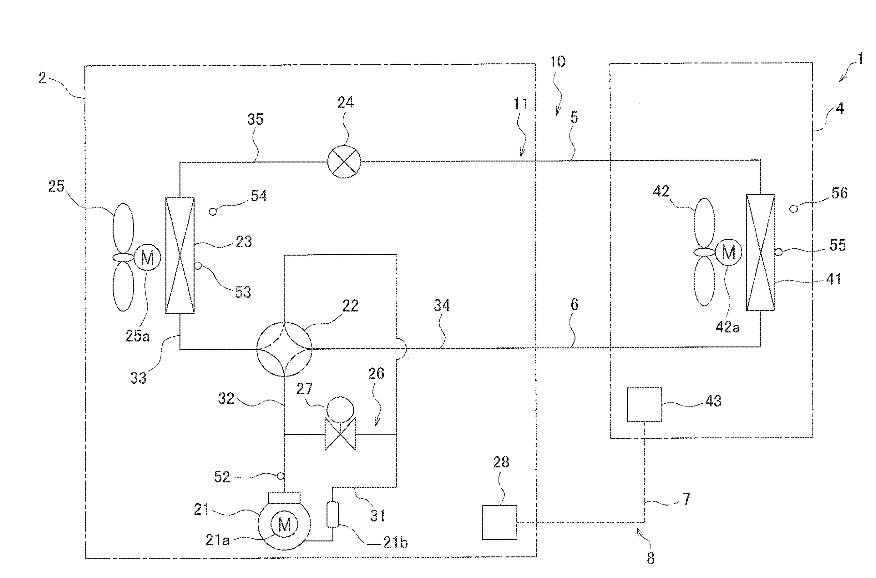
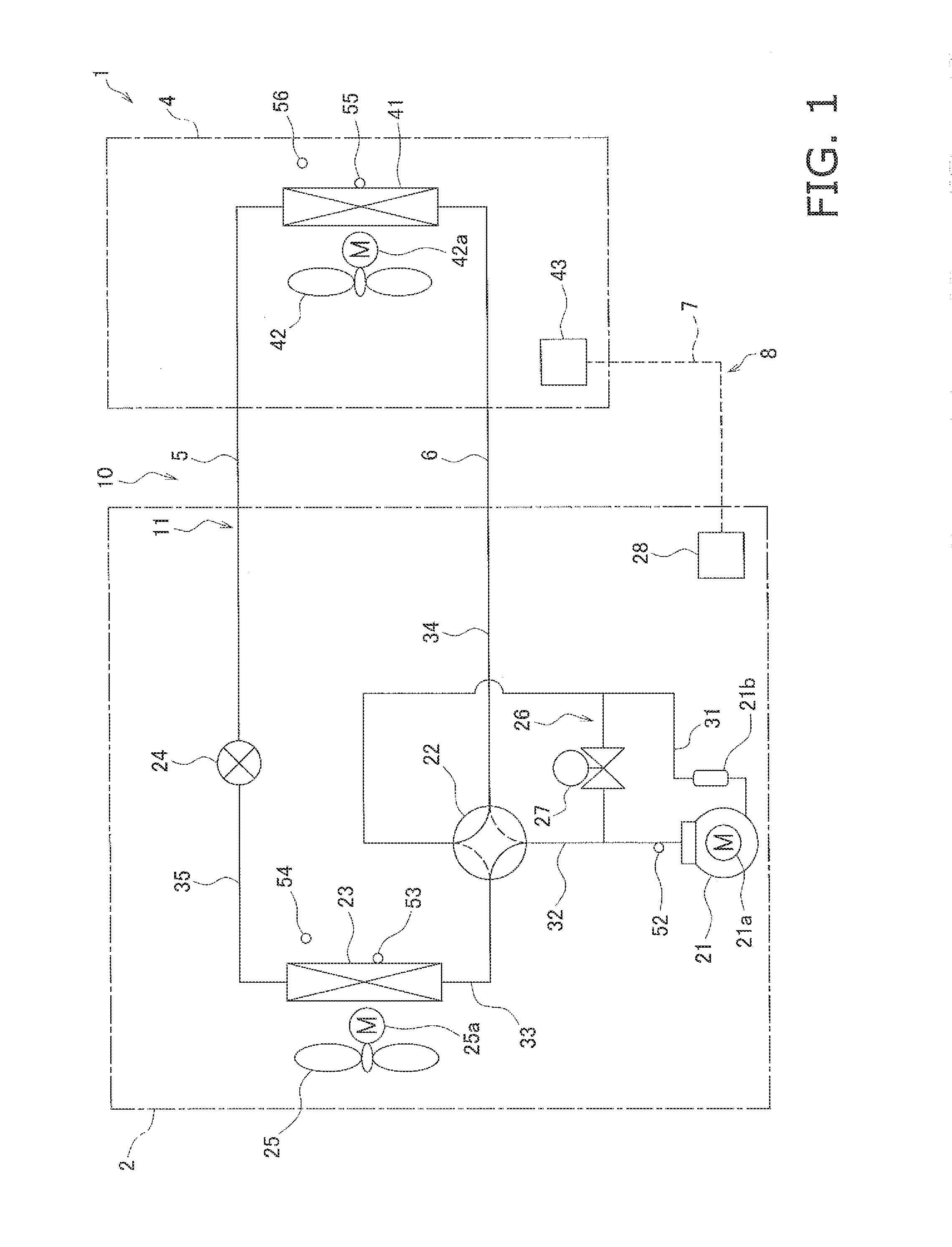
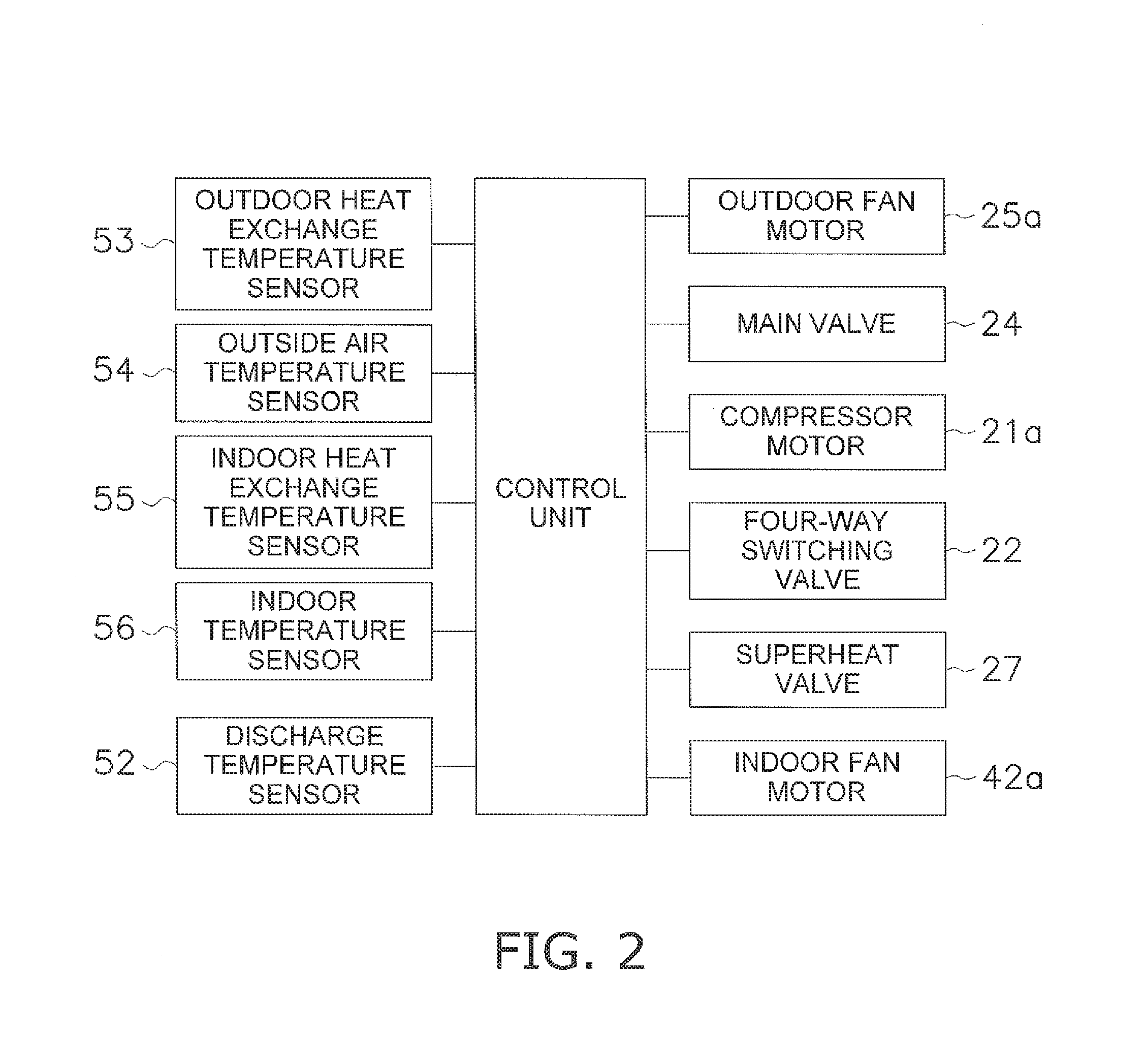
TECHNICAL FIELD[0001]The present invention relates to an air conditioning device, and in particular to an air conditioning device having a discharge-intake bypass circuit used during positive cycle defrosting mode, to defrost an outdoor heat exchanger while circulating a refrigerant through a compressor, an indoor heat exchanger, a main valve, and the outdoor heat exchanger, in the stated order.BACKGROUND ART[0002]In the prior art, there is described an air conditioning device like that indicated in Patent Literature 1 (Japanese Laid-open Patent Application No. 61-262560), having a compressor, an indoor heat exchanger, a throttle device (main valve), and an outdoor heat exchanger. This air conditioning device is capable of a heating mode in which a refrigerant is circulated through the compressor, the indoor heat exchanger, the main valve, and the outdoor heat exchanger in the stated order, and also has a discharge-intake bypass circuit allowing the refrigerant to bypass from the di...

Claims


Application Information

Patent Timeline
IPC IPC(8): F25B47/02F25B41/04F25B41/06F25B13/00
CPCF25B13/00F25B2700/2106F25B2313/02741F25B2313/0314F25B2313/0315F25B2400/04F25B2600/2501F25B2700/21152F25B2700/2104F25B2600/2513F25B2600/111F25B2341/065F25B41/062F25B41/04F24F2011/0089F25B47/025F25B47/02F24F11/42Y02B30/70F25B41/20F25B41/34
Inventor NUNO, HAYATOHAIKAWA, TOMOYUKI
Owner DAIKIN IND LTD
Why Eureka
Try Eureka