Computed tomography scanner calibration with angle correction for scan angle offset

a computed tomography and scanner technology, applied in the field of calibration and correction of projection data, can solve the problems of poor reconstructed image image quality, difference between actual and nominal angles,

Inactive Publication Date: 2016-08-18
TOSHIBA MEDICAL SYST CORP
View PDF3 Cites 23 Cited by
  • Summary
  • Abstract
  • Description
  • Claims
  • Application Information

AI Technical Summary

Problems solved by technology

This difference between actual and nominal angles can arise from the tolerance limitations in real-world measurement systems (e.g., backlash in the gears and resolution limitations of the measurement encoders).
Because the calibration projection data will likely have a different sub-view angular offset than the object projection data, without correcting for the differences in sub-view angular offset residual measurement artifacts remain after calibration corrections, resulting in poorer image quality for reconstructed images.

Method used


Image

  • Computed tomography scanner calibration with angle correction for scan angle offset
  • Computed tomography scanner calibration with angle correction for scan angle offset
  • Computed tomography scanner calibration with angle correction for scan angle offset

Examples


first embodiment

[0044]FIG. 3 shows a method 300 that is a method for matching the sub-view angular offsets between the calibration data and the object data. The method 300 is divided into two parts: a pre-acquisition calibration part and an object data acquisition part.

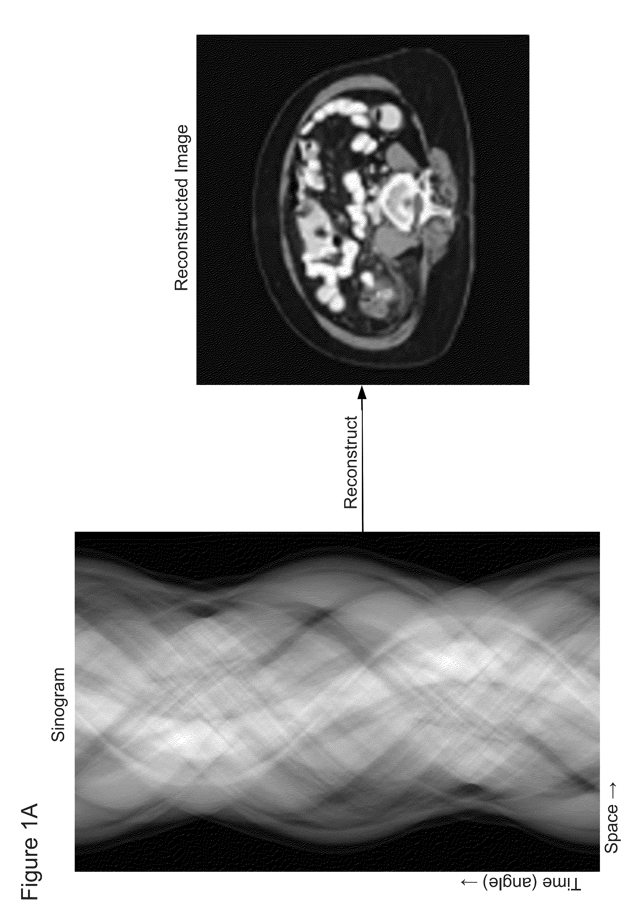
[0045]The pre-acquisition calibration part of method 300 begins with step 310 in which a calibration scan is performed. The calibration scan includes measuring X-ray projection data at a series of projection angles, wherein the object OBJ is a calibration object (e.g., either air or a predetermined phantom). After step 310, the pre-acquisition calibration part of method 300 proceeds to step 312, wherein the sinogram of the calibration data is interpolated and upsampled by a factor N, wherein the interpolation and upsampling is in the time / angle dimension, as shown in FIG. 1A.

[0046]The object data acquisition part of method 300 begins with step 320 by performing an object scan. Like the calibration scan 310, the object scan measures X...

second embodiment

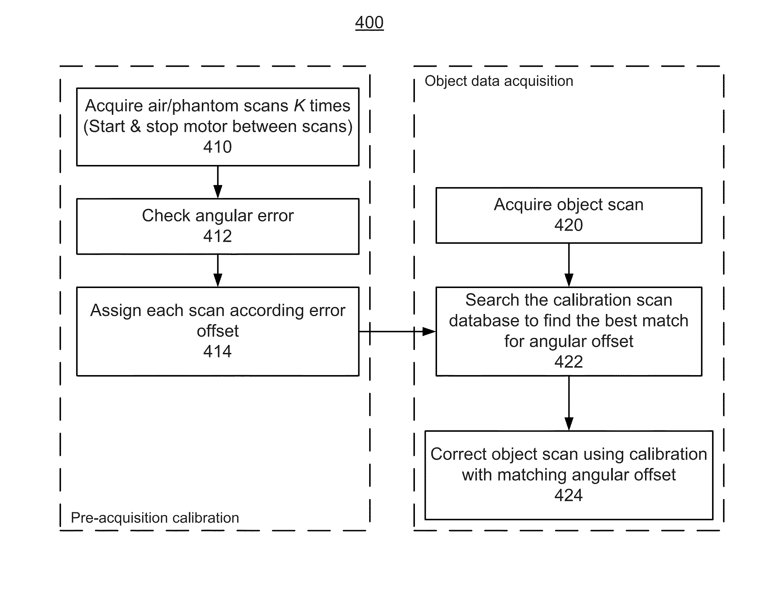
[0056]FIG. 4 shows a method for matching the sub-view angular offsets between the calibration data and the object data. The method 400 is divided into two parts: a pre-acquisition calibration part and a patient data acquisitions part.

[0057]The pre-acquisition calibration part of method 400 includes three steps: step 410, step 412, and step 414.

[0058]Step 410 includes acquiring multiple (K) calibration scans, where each scan includes a complete scan rotation of the CT scanner and the rotation is not continuous between scans (i.e., the rotation is stopped and then started between scans to obtain a unique offset angle for each scan). In one implementation, step 410 includes performing calibration scans to obtain the calibration data. In an alternative implementation, the calibration scans are performed prior to step 410 and the calibration data is stored in a computer readable medium. In this alternative implementation, step 410 includes obtaining the calibration data from the computer...


PUM


Abstract

A method and apparatus of aligning calibration projection data with object projection data to improve calibration corrections of the object projection data. In a first implementation, the method interpolates and upsamples both the calibration and object data, then shifts the upsampled calibration data to match a sub-view angular offset of the object data, and then performs calibration corrections before down-sampling the corrected object data. In a second implementation, the method continuously scans an object space—with the object absent (present) in the object space—to obtain calibration data (object absent) and object data (object present) both having the same sub-view angular offset. In a third implementation, the method obtains multiple scans having different sub-view angular offsets, organizes the scans into bins according to their respective sub-view angular offsets, and chooses the appropriate sub-view angular offsets bin for calibration corrections of the object data.

Description

BACKGROUND[0001]1. Field[0002]Embodiments described herein relate generally to calibrating and correcting projection data, and more specifically to matching the offset angle of the object projection data with the offset angle of calibration data, and then performing corrections to the object projection data using the calibration data.[0003]2. Description of the Related Art[0004]Computed tomography (CT) systems and methods are widely used, particularly for medical imaging and diagnosis. CT systems generally create images of one or more sectional slices through a subject's body. A radiation source, such as an X-ray source, irradiates the body from one side. A collimator, generally adjacent to the X-ray source, limits the angular extent of the X-ray beam, so that radiation impinging on the body is substantially confined to a planar region defining a cross-sectional slice of the body. At least one detector (and generally many more than one detector) on the opposite side of the body rece...

Claims


Application Information

Patent Timeline
Patent Type & Authority Applications(United States)
IPC IPC(8): G06T7/00A61B6/00H04N5/32A61B6/03
CPCG06T7/0024A61B6/032G06T2207/10116A61B6/4435H04N5/32A61B6/5211A61B6/4241A61B6/4266A61B6/488A61B6/582A61B6/583G06T11/005G16H50/20
Inventor YU, ZHOUZOU, YUZHANG, YUEXINGWANG, XIAOLAN
Owner TOSHIBA MEDICAL SYST CORP
Why Eureka
Try Eureka