

Battery, electrolyte, battery pack, electronic device, electric vehicle, power storage device, and power system
Active Publication Date: 2016-08-18
MURATA MFG CO LTD
View PDF7 Cites 43 Cited by
- Summary
- Abstract
- Description
- Claims
- Application Information
AI Technical Summary
Benefits of technology
The patent text claims that it can offer safety without reducing the capacity of a device.
Problems solved by technology
In the polymer battery, the shape variability is greatly improved by using an aluminum laminated film for the package member, but on the other hand, the strength may be insufficient and deformation is likely to occur when strong force is applied due to misuse.
In this case, although there is no problem in the case of being covered with a strong outer pack, the outer pack is becoming simpler with the recent requirement for higher capacities, and when the deformation is large, the battery is likely to experience a short circuit inside and may not function as a battery.
Method used
View moreImage
Smart ImageViewing Examples

Examples
first embodiment (
1. First embodiment (a first example and a second example of the battery)
second embodiment (
2. Second embodiment (an example of the battery pack)
third embodiment (
3. Third embodiment (an example of the battery pack)
Login to View More PUM
 Abstract
A particle size D50 of the particle is not less than 50 nm and not more than 450 nm, or not less than 750 nm and not more than 10,000 nm. A refractive index of the particle is not less than 1.3 and less than 2.4. One of a mass ratio between the particles and the matrix polymer compound (particles / matrix polymer compound) and a mass ratio between the particles and the electrolyte salt (particles / electrolyte salt) is not less than 15 / 85 and not more than 90 / 10.
Description
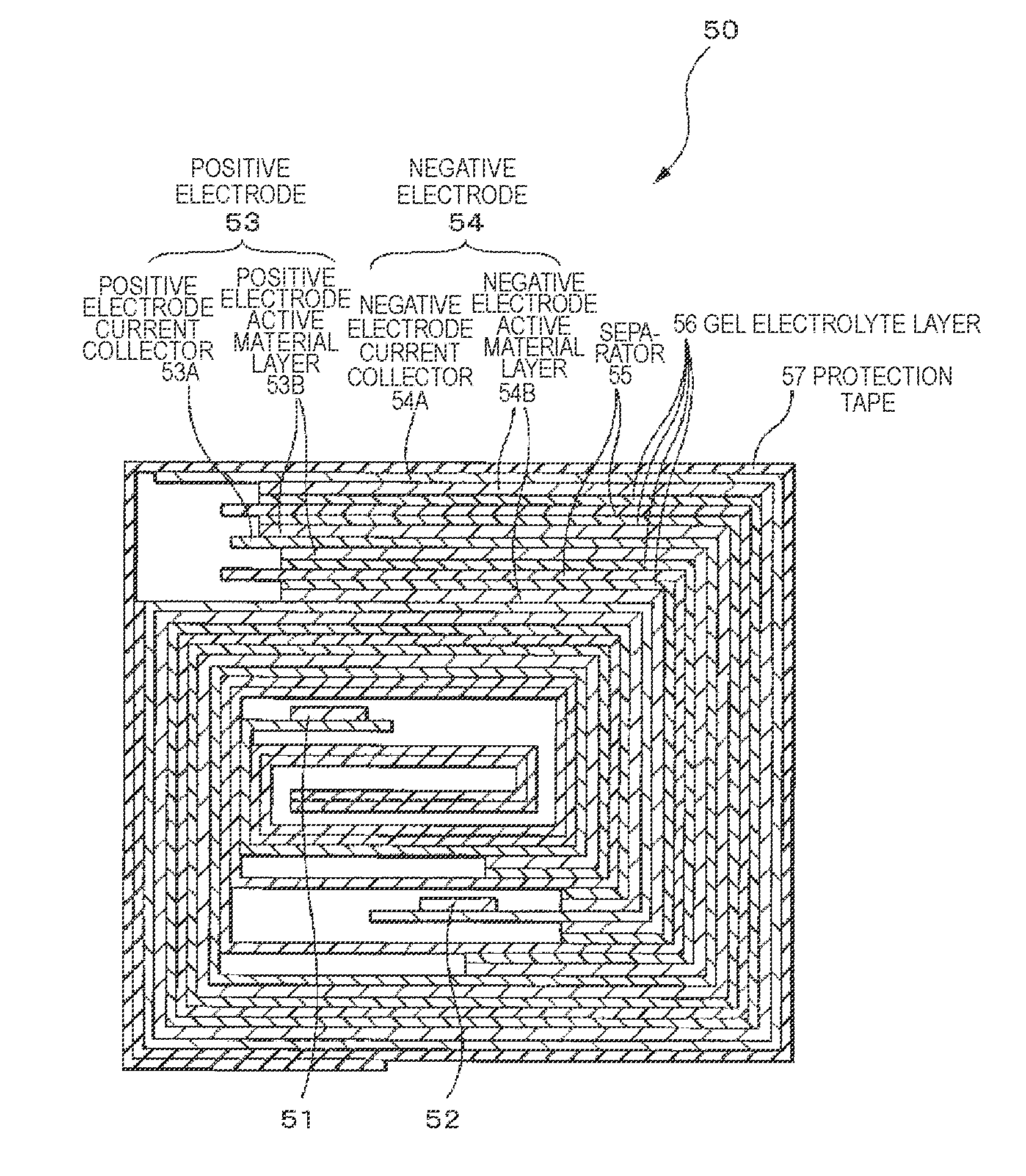
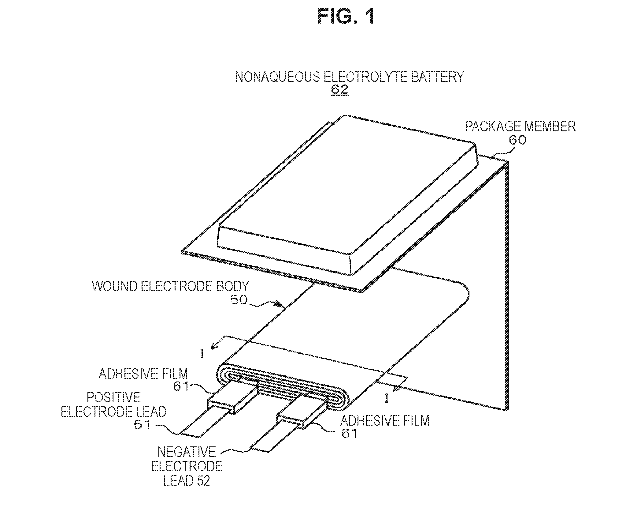
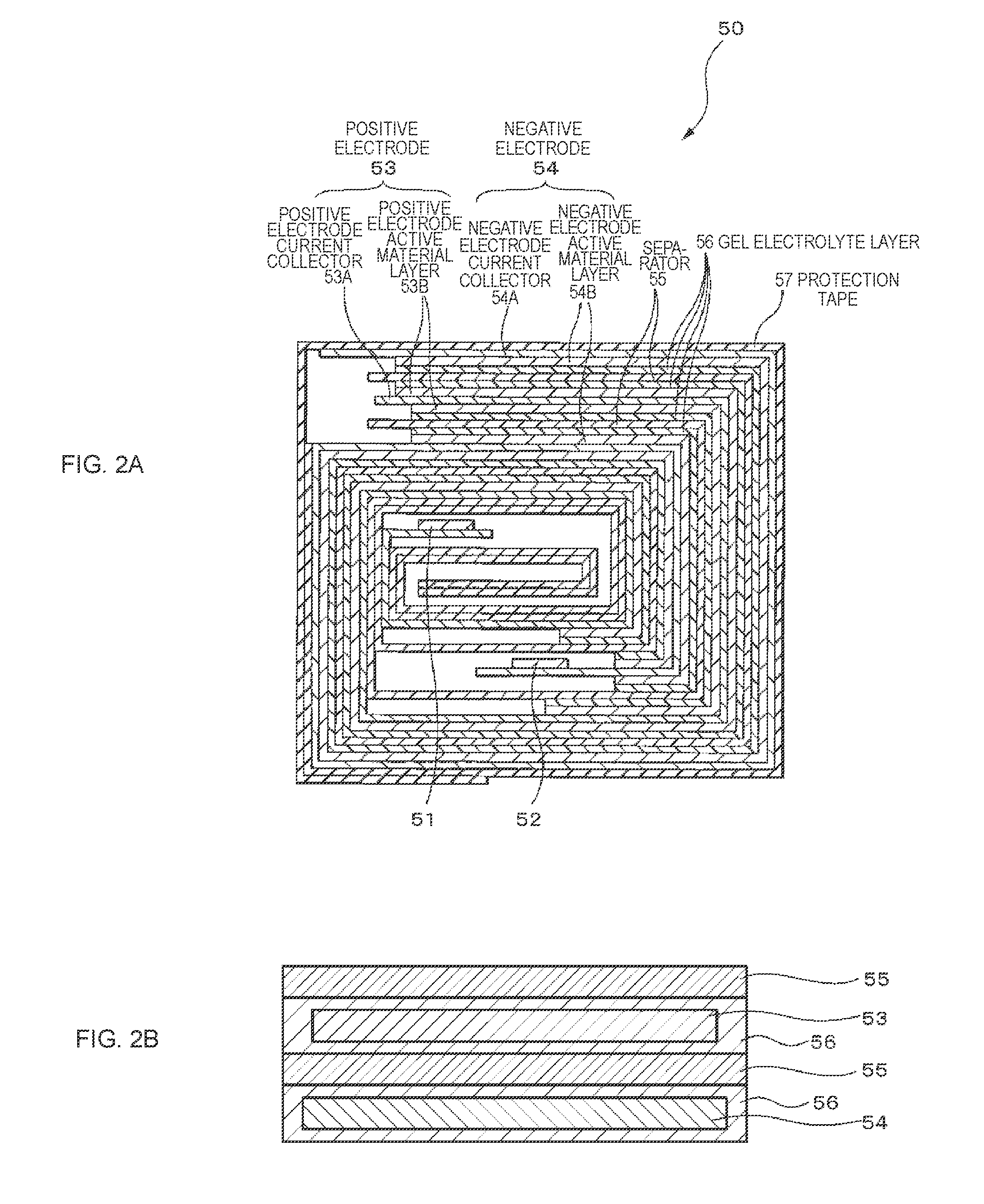
TECHNICAL FIELD[0001]The present technology relates to a battery, an electrolyte, a battery pack, an electronic device, an electric vehicle, a power storage device, and a power system each using the battery.BACKGROUND ART[0002]For lithium ion secondary batteries, which are excellent in energy density and are widely used for mobile devices, those using a laminated film for the package member are put in practical use because of their lighter weight and high energy density, the manufacturability of batteries with a very thin shape, etc.[0003]In the battery thus using a laminated film as the package member, an electrolyte solution and a polymer compound are used as the electrolyte for the purposes of resistance to liquid leakage etc., and such a battery is known as a polymer battery. Among them, a battery using a gel electrolyte in what is called a gel form in which an electrolyte solution is retained in a polymer compound is widely used.[0004]In the polymer battery, the shape variabili...
Claims
Login to View More Application Information
Patent Timeline
 IPC IPC(8): H01M10/0565H01M10/46H01M4/131H01M4/133H01M4/525B60L11/18H01M4/62H01M4/66H01M10/0587H01M2/02H01M2/06H01M2/30H01M10/42H01M4/587H01M50/105H01M50/178H01M50/55H01M50/553
CPCH01M4/13Y02E60/122H01M10/48H01M2010/4278H01M2220/20H01M2300/0085H01M2300/0091H01M2004/027H01M2300/004H01M10/0587H01M4/661H01M4/625H01M4/623H01M4/622H01M4/587H01M4/525H01M4/1393H01M4/1391H01M4/133H01M4/131H01M4/0404H01M2/305H01M2/30H01M2/06H01M2/024H01M2/021B60L11/1861B60L11/1811H01M2220/30H01M2010/4271H01M2004/028H01M10/46H01M10/052H01M10/0565Y02T10/7011H01M10/4257H01M10/0585H01M10/482H01M10/486B60L53/20B60L58/15Y02E60/10Y02T10/70Y02T10/7072Y02T90/14Y02P70/50H01M50/553H01M50/178H01M50/105H01M50/55H01M10/056
InventorHATTA, KAZUHITOKAGAMI, KEIICHISHIMOSAKA, NOBUAKIKOGA, KEIZO
OwnerMURATA MFG CO LTD