Pneumatic tire

a technology of pneumatic tires and treads, applied in the field of pneumatic tires, can solve the problems of reducing wear resistance, achieve excellent edge effect, maintain wear resistance, and improve on-ice performan

Active Publication Date: 2016-08-25
SUMITOMO RUBBER IND LTD
View PDF3 Cites 9 Cited by
  • Summary
  • Abstract
  • Description
  • Claims
  • Application Information

AI Technical Summary

Benefits of technology

[0015]The pneumatic tire of the present invention includes the tread portion provided with a pair of circumferentially and continuously extending central main grooves on both sides of the tire equator, and a circumferentially and continuously extending central narrow groove disposed on axially inward of the central main grooves and having a width smaller than the central main grooves. Owing to the central narrow groove, the rigidity of a land portion between the central main grooves in which large ground contact pressure acts is maintained, and the wear resistance is maintained.
[0016]The central narrow groove includes a first central narrow groove extending along the tire circumferential direction and a second central narrow groove extending in a zigzag shape. These first central narrow groove and second central narrow groove can exhibit excellent edge effect, and can improve the on-ice performance.
[0017]The first central narrow groove is disposed axially inward of the second central narrow groove. That is, the first central narrow groove is disposed on the side of the tire equator of the tread portion on which a large ground pressure acts. Thus, when running on ice, an edge component extending in the circumferential direction of the tire of the first central narrow groove can exhibit a large frictional force in the axial direction of the tire. Moreover, when cornering, zigzag edges of both second central narrow grooves 6 are engaged one another. Thus, land portions disposed on both sides of the second central narrow groove 6 are integrated, and the rigidity of the land portion between the central main groove and the first central narrow groove is improved. Therefore, the pneumatic tire according to the present invention can improve the wear resistance.
[0018]As described above, the pneumatic tire of the present invention can achieve both the on-ice performance and the wear resistance.

Problems solved by technology

Unfortunately, the tire provided with the sipe has a problem that the wear resistance is reduced since the rigidity of a land portion is reduced.

Method used


Image

  • Pneumatic tire
  • Pneumatic tire
  • Pneumatic tire

Examples


example

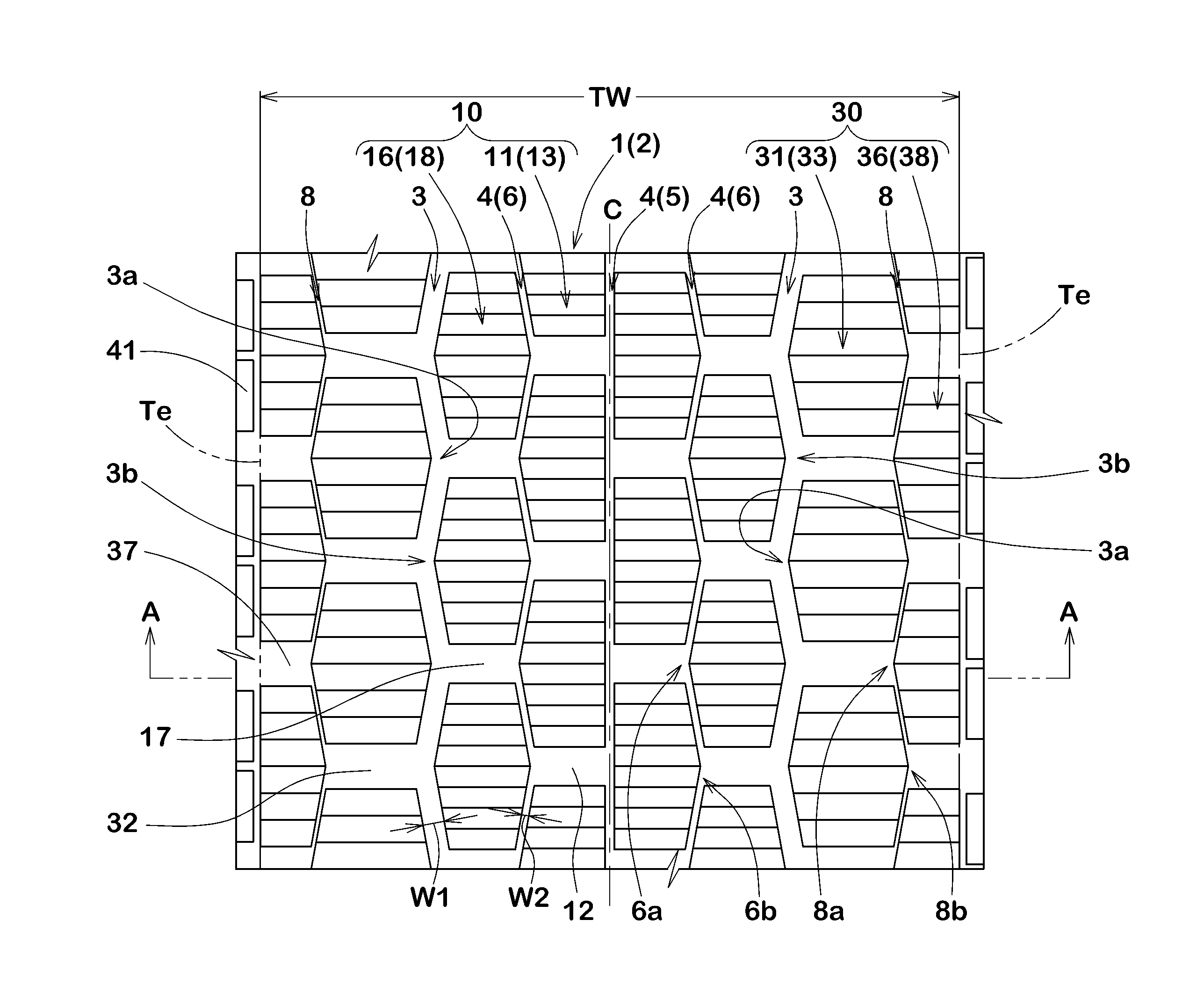
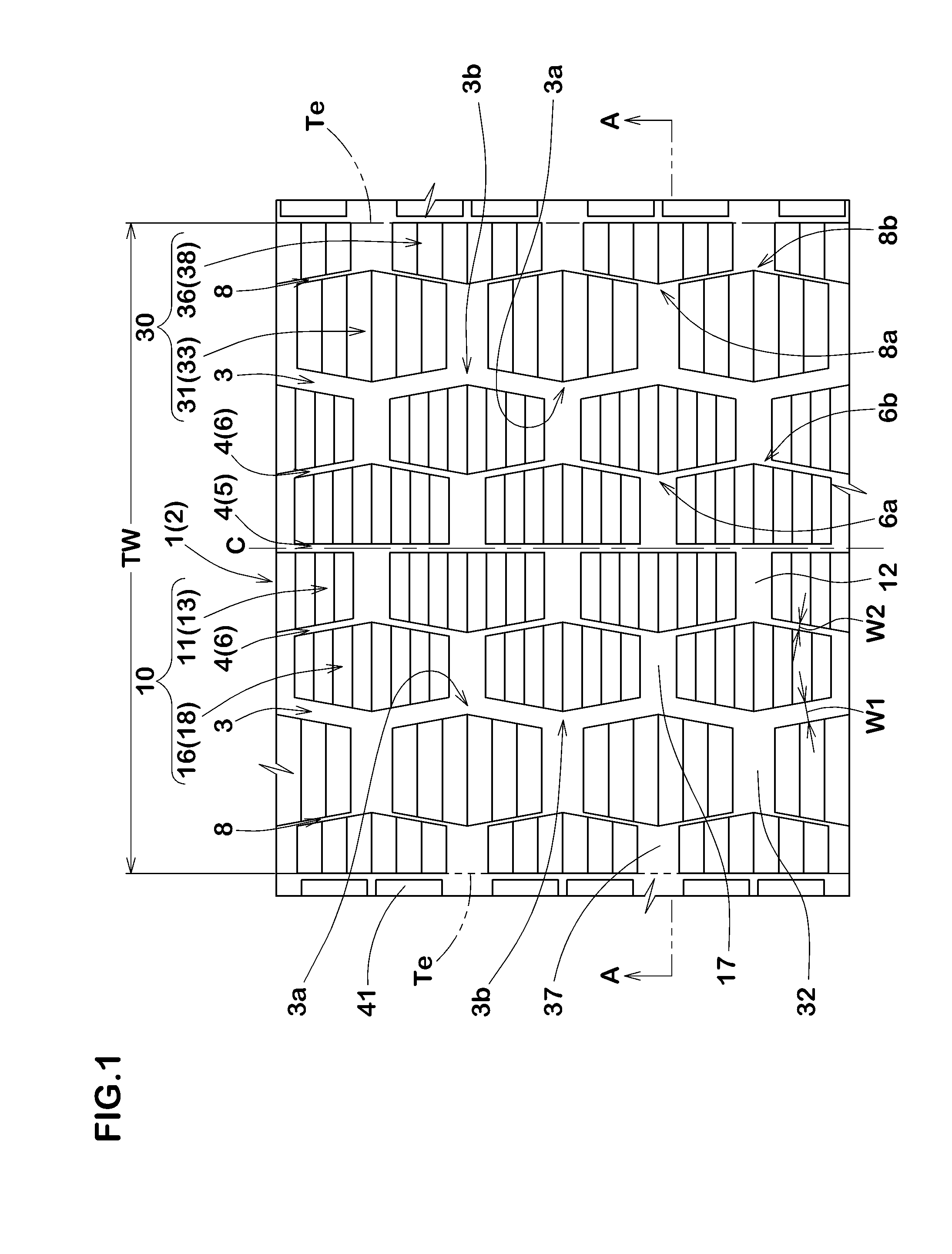
[0082]Heavy duty pneumatic tires of a size 11R22.5 having the basic pattern of FIG. 1 were manufactured based on the specifications shown in Table 1. As Comparative Example 1, a tire having no central narrow groove was manufactured. As Comparative Example 2, regarding narrow grooves between the central main grooves, the tire which is provided with only a straight first central narrow groove was manufactured. Then, for each test tire, on-ice performance, on-snow performance, and wear resistance were evaluated. Common specifications and test methods for each test tire is as follows.

[0083]Rim: 8.25×22.5

[0084]Tire inner pressure: 900 kPa

[0085]Test vehicle: 10-ton truck, carrying 50% of the load of standard load capacity in carrier central

[0086]Tire Mounting Position: All-Wheel

[0087]On-Ice Performance:

[0088]On-ice performance was evaluated by a driver's feeling using the test vehicle fitted with the test tire. The results are indicated using a score wherein Comparative Example 1 is set t...


PUM


Abstract

A pneumatic tire in which a tread part is provided with a pair of central main grooves extending continuously around the circumference of the tire on both sides of a tire equator C, and central thin grooves extending continuously around the circumference of the tire on the tire-axially inner sides of the central main grooves and having less groove width than the central main grooves. The central thin grooves include a linear first central thin groove running along the tire circumference, and zigzagging second central thin grooves. The first central thin groove is provided on the tire-axially inner sides of the second central thin grooves.

Description

TECHNICAL FIELD[0001]The present invention relates to a pneumatic tire that combines on-ice performance and wear resistance.BACKGROUND ART[0002]Conventionally, to improve a running performance on ice (hereinafter, referred to as an “on-ice performance”), a pneumatic tire including a tread block with a sipe has been proposed. Such a pneumatic tire can exhibit the on-ice performance by an action of scratching the ground using edges of the sipe (hereinafter, referred to as an “edge effect”), and a water-absorption effect and the like.[0003]Unfortunately, the tire provided with the sipe has a problem that the wear resistance is reduced since the rigidity of a land portion is reduced.[0004]The following Patent Document 1 proposes a pneumatic tire including axially extending lateral grooves arranged at improved pitches. In such a pneumatic tire, rubber chipping of a block between lateral grooves is suppressed. Thus, wear resistance of the land portions can be improved.[0005]Patent Documen...

Claims


Application Information

Patent Timeline
Patent Type & Authority Applications(United States)
IPC IPC(8): B60C11/03
CPCB60C2011/0334B60C2011/0393B60C2011/0358B60C11/0327B60C11/033B60C11/12B60C2011/013B60C11/0306B60C2011/0367B60C2011/1209B60C2011/0355B60C11/1236B60C2011/129B60C11/11B60C2011/0344B60C2011/0346B60C2011/0353B60C2011/0365B60C2011/0348
Inventor ITO, TADASHI
Owner SUMITOMO RUBBER IND LTD
Why Eureka
Try Eureka