Supercharge Your Innovation With Domain-Expert AI Agents!

Turbo engine with torsional coupling integrated to at least one driving or driven shaft driving

a technology of torsional coupling and turbo engine, which is applied in the direction of non-positive displacement fluid engine, liquid fuel engine components, pump components, etc., can solve the problems of complex layout of shaft assembly, manufacturing problems, and present fragility zones

Inactive Publication Date: 2016-08-25
THERMODYN
View PDF2 Cites 2 Cited by
  • Summary
  • Abstract
  • Description
  • Claims
  • Application Information

AI Technical Summary

Benefits of technology

The present invention aims to improve the performance and layout of turbo engines by integrating a torsional coupling in the shaft assembly. This torsional zone allows for better support of the axial efforts during the compression levels, while also reducing the size, weight, and cost of the engine. Additionally, the reduced size of the shaft assembly helps to improve the dynamics of the rotor.

Problems solved by technology

This solution poses in a certain number of cases manufacturing problems and problems related to the dynamic of the rotor.
In addition, they present a fragility zone because they can be subjected, for example, only to tensile or compression forces that are limited in the axial direction.
Although it is effective in alleviating the inconveniences related to the use of a flexible coupling between the driving shaft and the driven shaft, such a layout complicates the structure of the shaft assembly.

Method used


Image

  • Turbo engine with torsional coupling integrated to at least one driving or driven shaft driving
  • Turbo engine with torsional coupling integrated to at least one driving or driven shaft driving

Examples


Embodiment Construction

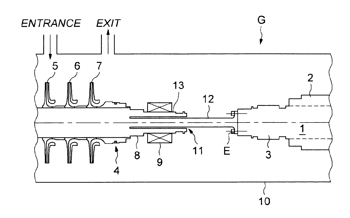
[0032]Referring first to FIG. 1, a motor-driven compressor according to an embodiment of the present invention, designated by the general reference G, comprises essentially a motor 1, for example an electric motor with high rotational speed, for example between 6,000 and 16,000 revolutions / minute, powered by a frequency converter and comprising a stator 2 and a rotor 3 forming a driving shaft for the motor-driven compressor group, and a compressor group 4 comprising a set of wheels with blades 5, 6 and 7, here three in number, mounted on the driven shaft 8. As it can be seen, the driven shaft 8 is supported by the radial bearings 9.

[0033]The arrangement is mounted on a base (not shown) and is located in a common casing 10, which is impermeable to the gas generated by the motor-driven compressor group. The casing 10 comprises an input “INPUT”, through which the gas to be generated is drawn by suction into the compressor and an output “OUTPUT”, through which the compressed gas is deli...


PUM


Abstract

A turbo engine comprises a driving shaft and a driven shaft actuated by the driving shaft being coupdriven to this driving shaft by means of a torsional coupling. The torsional coupling is integrated at least into one of the driven and driving shafts comprising a zone that is rotationally flexible, in such a way as to constitute the torsional coupling.

Description

BACKGROUND[0001]Embodiments of the present invention relate to turbo engines, for example integrated motor-driven compressors. However, of course one does not go outside the framework of embodiments of the present invention merely because it relates to another type of turbo engine, namely a turbo alternator.[0002]An integrated motor-driven compressor group comprises a leakproof housing which contains an engine, for example an electric motor, and a compressor group, for example a multi-stage unit, which comprises one or several wheels with blades for compression carried by a driven driven shaft and actuated by a driving driving shaft consisting of the rotor of the motor or actuated by the latter.[0003]One coupling solution for the driving shaft and the driven shaft consists in a coupling of the driven shaft and the driving shaft by means of a rigid coupling, with bearings provided for supporting the ends of the line of shafts of the motor-driven compressor group, as well as its media...

Claims


Application Information

Patent Timeline
Patent Type & Authority Applications(United States)
IPC IPC(8): F01D5/02F04D29/054F04D25/02
CPCF01D5/026F04D25/022F04D29/054F04D29/044
Inventor JEVARDAT DE FOMBELLE, GUILLAUMEFAYARD, DOMINIQUE
Owner THERMODYN
Features
  • R&D
  • Intellectual Property
  • Life Sciences
  • Materials
  • Tech Scout
  • Unparalleled Data Quality
  • Higher Quality Content
  • 60% Fewer Hallucinations
Learn More