
Braking mechanism and load support mechanism

Inactive Publication Date: 2016-08-25
COPYER
View PDF2 Cites 1 Cited by
  • Summary
  • Abstract
  • Description
  • Claims
  • Application Information

AI Technical Summary

Benefits of technology

The present invention provides a braking mechanism that prevents a decrease in braking force with a pressing position, even after brake surface wear. This is achieved by a new pressing position that compensates for worn out brakes, and by inclining the brake surface to increase friction. These features enable a brake device to maintain strong braking performance over long periods of use.

Problems solved by technology

In conventional brake devices, such as the one disclosed in Patent Document 1, the repeated shift of a to-be-braked body between a moving state and a braked state causes a braking force to weaken, as a brake shoe, especially only a portion being pressed by the brake shoe, wears out earlier due to friction each time it is used.

Method used


Image

  • Braking mechanism and load support mechanism
  • Braking mechanism and load support mechanism
  • Braking mechanism and load support mechanism

Examples


first embodiment

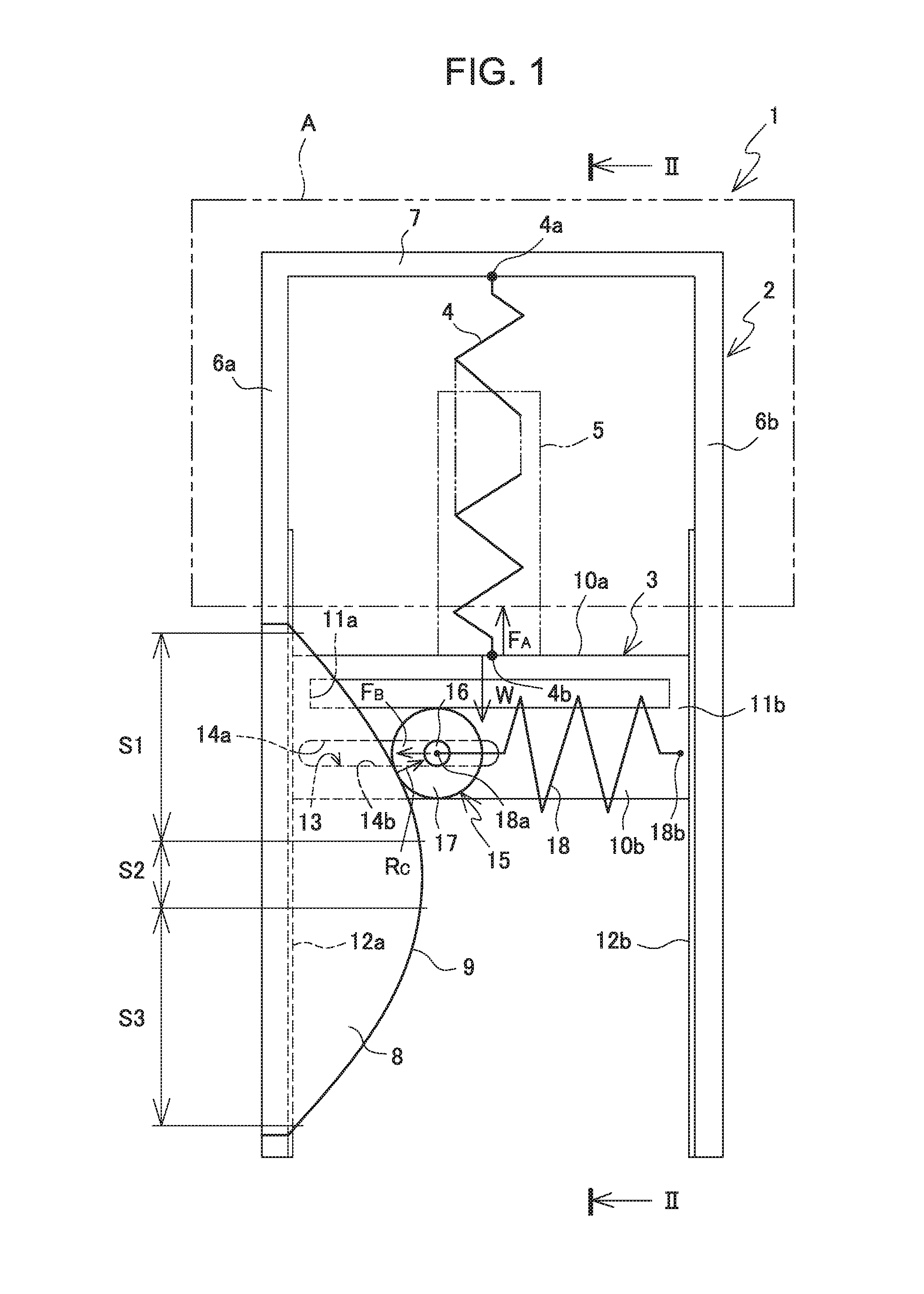
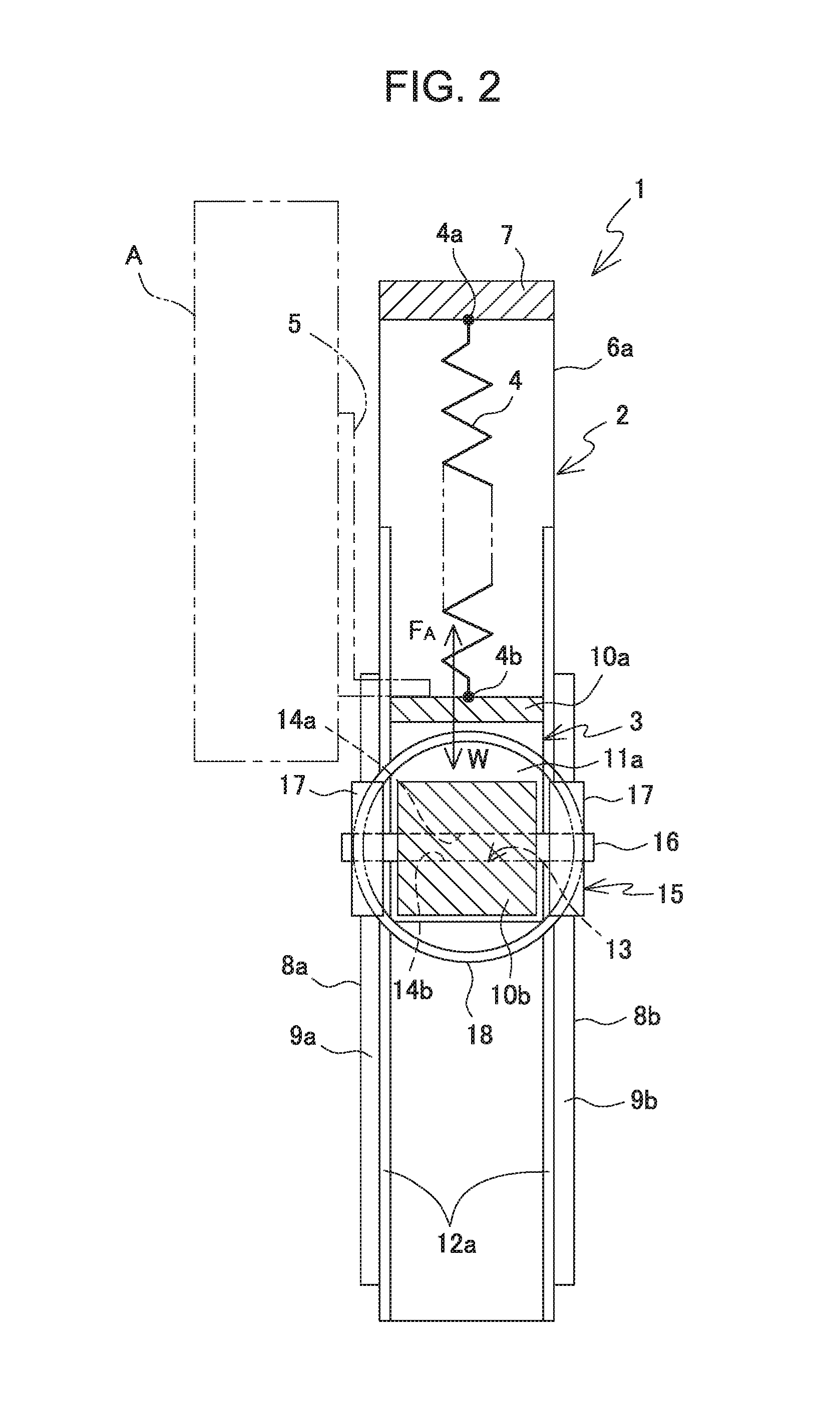
[0100]FIGS. 6 to 8 show an article support device to which such a modified example of the present invention has been specifically applied. An article support device 20 of the present embodiment is designed to support a relatively heavy article B, such as a large-screen television monitor. The article support device 20 includes a base 21, which is placed on a floor surface or the like in a movable manner; a fixed frame section 22, which is fixed to the base; a support frame section 23, which is mounted on the fixed frame section in such a way as to be able to move up and down; a first sprint 24; and an operation handle section 25, which is used to move up or down the support frame section 23.

[0101]As described later, the article B is integrally attached to the support frame section 23 in a detachable manner. A lower portion of the fixed frame section 22 is erected and firmly fixed by stays 21b to an upper surface of a base plate 21a of the base 21.

[0102]The fixed frame section 22 is ...

second embodiment

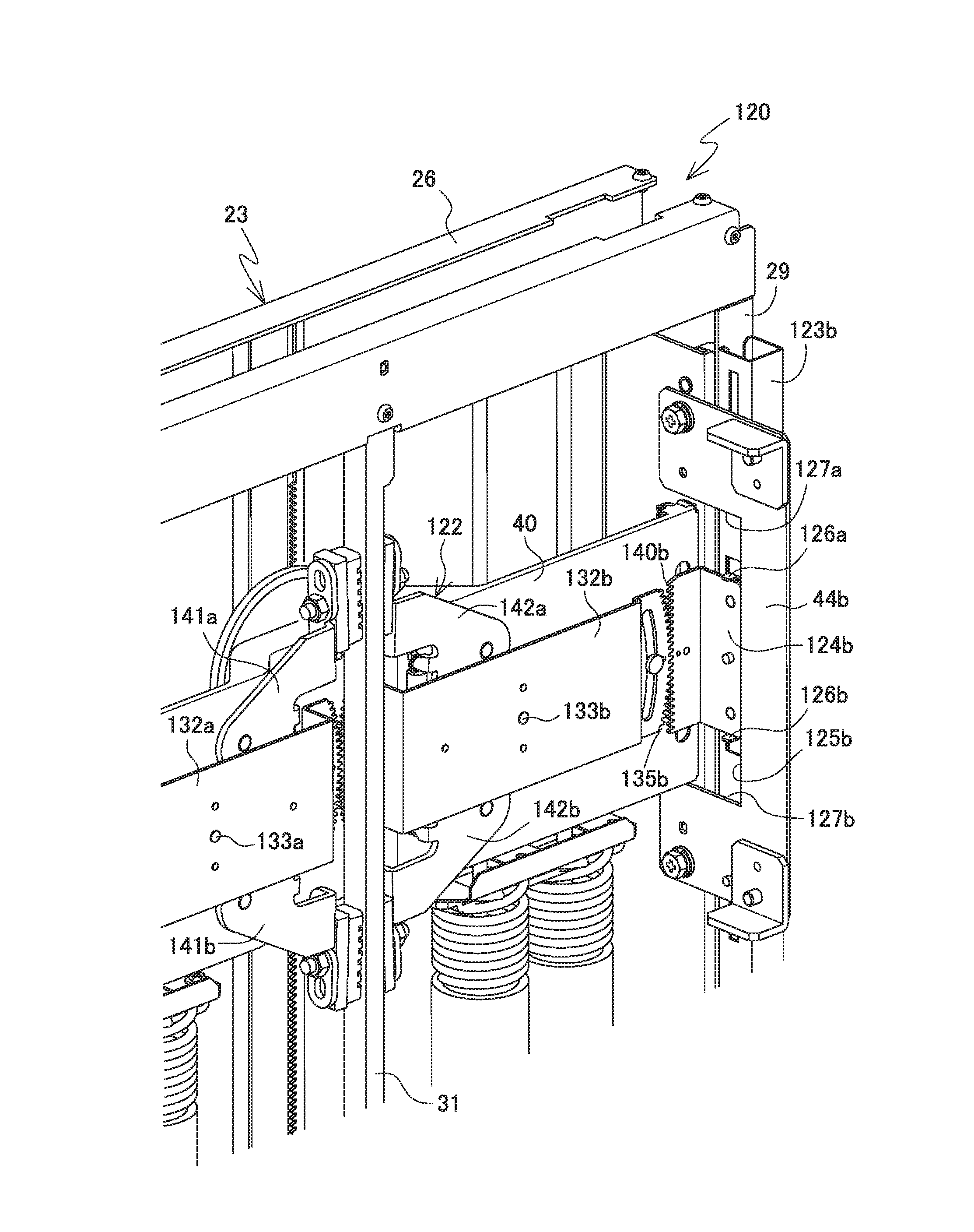
[0236]In the article support device 120 of the second embodiment, regardless of the rigidity of the support frame section 23, the predetermined rectangular frame structure can be kept at any time when moving. Even when a heavy or large article is to be supported, the higher-than-required rigidity of the rectangular frame structure of the support frame section 23 is unnecessary. When a relatively light or small article is to be supported, the predetermined rectangular frame structure can be kept at any time and moved smoothly even if the rigidity of the support frame section 23 is decreased accordingly.

[0237]An improved type of the above-described brake device 122 (brake portion) of the second embodiment of FIGS. 29 to 34 will be explained. The brake device repeats the operation of exerting and cancelling the braking on the first brake rail 31. When the braking is to be exerted, the braking is being applied as the situation sequentially shifts from FIG. 34 to FIG. 33 and to FIG. 32.

[...


PUM


Abstract

The present invention is to provide a brake mechanism that prevents a significant decrease in braking force, even after years of being used with a repeat of braking and cancellation by a brake portion and a to-be-braked portion. A brake device 122 includes brake pads 145a, 145b, 146a, and 146b, which engage with or depart from a side of a first brake rail, on tips of upper and lower pairs of brake arms 141a, 141b, 142a, and 142b, which are provided in a rotatable manner across the first brake rail 31. When the brake pads 145a, 145b, 146a, and 146b are pressed against the brake rail 31, the brake pads are disposed in such a way as to be inclined so that a gap 304 emerges on a base end portion 302's side that is close to a fulcrum 144a's side.

Description

BACKGROUND OF THE INVENTION[0001]1. Technical Field[0002]The present invention relates to a braking mechanism for controlling movement of an object. In particular, the present invention relates to a braking mechanism that is suitably used in a load support mechanism that supports a target article at a desired position in such a way as to be able to move the target article, as well as to the load support mechanism.[0003]2. Description of the Related Art[0004]In general, a support mechanism that supports various articles, such as a computer, a television monitor device, a top plate of an OA desk or work table, and a heavy object, at a desired height position in such a way as to be able to move the articles up and down preferably includes a braking mechanism to carry out or cancel braking of movement of the articles, thereby ensuring safety at the time of use. For example, an elevator that lifts a car up and down by winching a rope using a winch sheave includes a brake device; the brak...

Claims


Application Information

Patent Timeline
IPC IPC(8): F16D63/00F16M11/22F16M11/18F16M11/04
CPCF16D63/008F16M11/046F16M2200/027F16M11/18F16M11/22F16B1/02B60T1/14B61H9/02F16M11/42F16M2200/047
Inventor AOYAGI, TATSUZOAKIYAMA, HIROTOOCHIAI, TORU
Owner COPYER
Features
  • Generate Ideas
  • Intellectual Property
  • Life Sciences
  • Materials
  • Tech Scout
  • Unparalleled Data Quality
  • Higher Quality Content
  • 60% Fewer Hallucinations
Learn More