Semifinished wire with PIT elements for a superconducting wire containing Nb3Sn and method of producing the semifinished wire
a superconducting wire and semi-finished technology, applied in the direction of superconductors/hyperconductors, electrical devices, insulation conductors/cables, etc., can solve the problems of aggravated semi-finished wire handling and relatively soft tin, and achieve good deformation behavior
- Summary
- Abstract
- Description
- Claims
- Application Information
AI Technical Summary
Benefits of technology
Problems solved by technology
Method used
Image
Examples
first embodiment
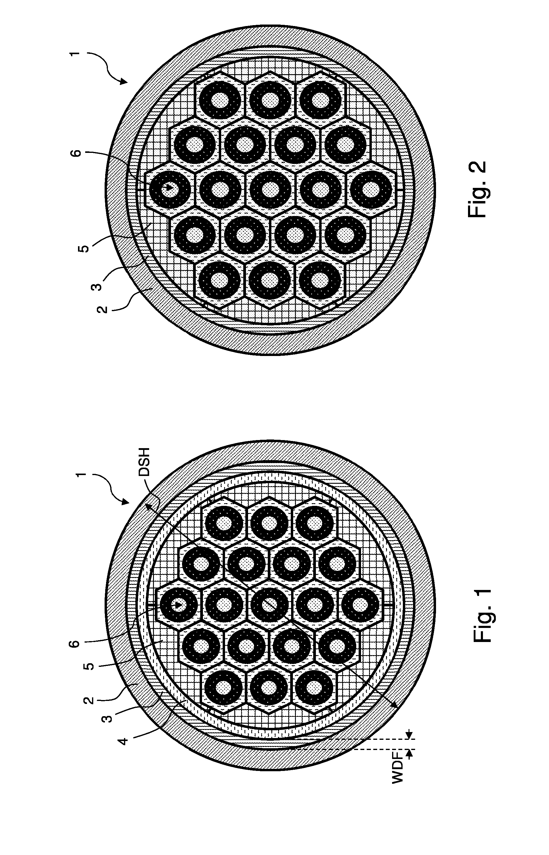
[0081]FIG. 1 shows a schematic cross-sectional view of an inventive semifinished wire 1.
[0082]On its radial outer side, the semifinished wire 1 has a Cu stabilization cladding tube 2 which is produced from high purity copper (typically with a purity of 99.9 atom % or more). The Cu stabilization cladding tube 2 has a circular outer and inner cross-section in the present case. The percentage of area of the Cu stabilization cladding tube 2 with respect to the overall area of the semifinished wire 1 in cross-section is preferably approximately 22-27%, usually 24-25%, and the outer diameter DSH of the Cu stabilization cladding tube 2 or of the semifinished wire 1 is preferably approximately 0.6-0.9 mm, usually 0.7-0.85 mm.
[0083]A tubular diffusion barrier 3 with a ring-shaped closed cross-section abuts the inner side of the Cu stabilization cladding tube 2. In the present case, the diffusion barrier 3 is produced from niobium and preferably has a wall thickness WDF of 10-20 μm. The perce...
second embodiment
[0088]FIG. 2 shows a schematic cross-section of an inventive semifinished wire 1 similar to the embodiment shown in FIG. 1. For this reason, only the substantial differences are explained.
[0089]In the embodiment illustrated in FIG. 2, the filler elements 5 directly abut the diffusion barrier 3 on the outer side. An inner element is not provided. For this reason, it is possible to provide more area for the PIT elements 6 in the inside of the diffusion barrier 3. The PIT elements 6 can correspondingly move closer to the diffusion barrier 3.
third embodiment
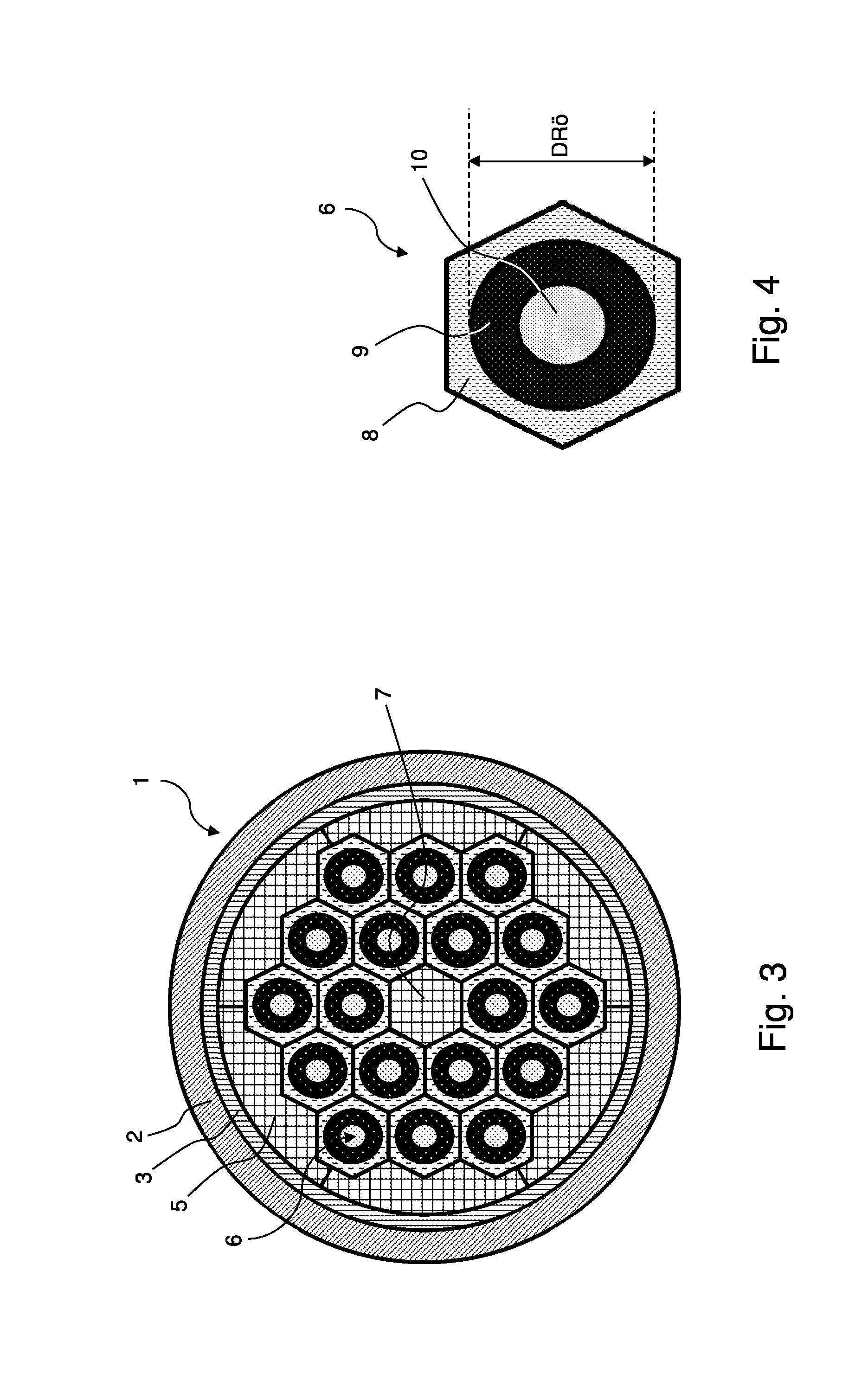
[0090]FIG. 3 shows a schematic cross-section of an inventive semifinished wire 1 similar to the embodiment illustrated in FIG. 2. For this reason, only the substantial differences are explained.
[0091]In the embodiment illustrated in FIG. 3, a central filler element 7 is provided in the inside of the bundle of 18 PIT elements 6 in the present case, the filler element taking up a space that corresponds to a hexagonal PIT element. It should be noted that the taken-up space in other embodiments can also correspond to a plurality of PIT elements, e.g. three or seven or more. The central filler element 7 is typically produced from the same material as the filler elements 5, e.g. of copper. The central filler element 7 avoids high mechanical load on PIT elements in case of cross-section-reducing shaping.
[0092]FIG. 4 shows a schematic cross-section of an individual PIT element 6 for an inventive semifinished wire as shown e.g. in FIGS. 1 to 3.
[0093]The PIT element 6 has a cladding 8 contain...
PUM
 Abstract
Description
Claims
Application Information
 - R&D
- Intellectual Property
- Life Sciences
- Materials
- Tech Scout
- Unparalleled Data Quality
- Higher Quality Content
- 60% Fewer Hallucinations
Browse by: Latest US Patents, China's latest patents, Technical Efficacy Thesaurus, Application Domain, Technology Topic, Popular Technical Reports.
© 2025 PatSnap. All rights reserved.Legal|Privacy policy|Modern Slavery Act Transparency Statement|Sitemap|About US| Contact US: help@patsnap.com


