Cracking detection system and cracking detection method

a detection system and cracking technology, applied in the field of crack detection methods, can solve problems such as reducing safety and reducing safety

Inactive Publication Date: 2016-09-01
SAGA UNIVERSITY +1
View PDF0 Cites 10 Cited by
  • Summary
  • Abstract
  • Description
  • Claims
  • Application Information

AI Technical Summary

Benefits of technology

[0029]The magnitude of strain on the surface, which is caused when applying the heat, becomes large with increased amount of thickness in the detection object, and in case where the crack passes completely through to the other side, the strain in each of tensile and compression directions becomes the largest, and a magnitude of strain in a group of strains indicating the crack has a similar tendency also in the strain distribution, which has been acquired from the images as taken when before and after applying the heat. In the present invention, by acquiring previously the strain distribution from the images, as taken before and after applying the heat, of a certain surface and the opposite surface to which the crack reaches, in a predetermined area, which include, for example, the crack passing partially through to the other side, of the detection object itself, or a body formed of the same material as the part to be detected, of the detection, and by confirming the magnitude of strain in each of a passing-through portion of the crack and a non-passing-through portion of the crack to determine a relationship of them, it is therefore possible to determine the depth of the crack based on the magnitude of strain, even for a group of strains indicating the crack in the strain distribution of the part to be detected, and detect easily an existence of the passing-through portion of the crack in the part to be detected and the crack depth, based on the strain distribution, thus saving many steps to measure for every cracks and achieving confirmation of the condition of the crack in a short period of time.

Problems solved by technology

With respect to steel structures such as a bridge or the like, an appropriate maintenance work is required for these structures so that aged deterioration in load bearing ability and durability of such structures may not reduce the safety of them.
Especially, under some circumstances where external forces are repeatedly applied to steel materials of the steel structure, for example, in a bridge to which a load is repeatedly applied along with the passage of vehicles, cracks may occur in places such as welded portions in which stress may easily concentrate, and such cracks may cause an event reducing the safety, such as fracture of the steel material, and accordingly, there is a strong demand to detect early the cracks.

Method used


Image

  • Cracking detection system and cracking detection method
  • Cracking detection system and cracking detection method
  • Cracking detection system and cracking detection method

Examples


first embodiment

of the Present Invention

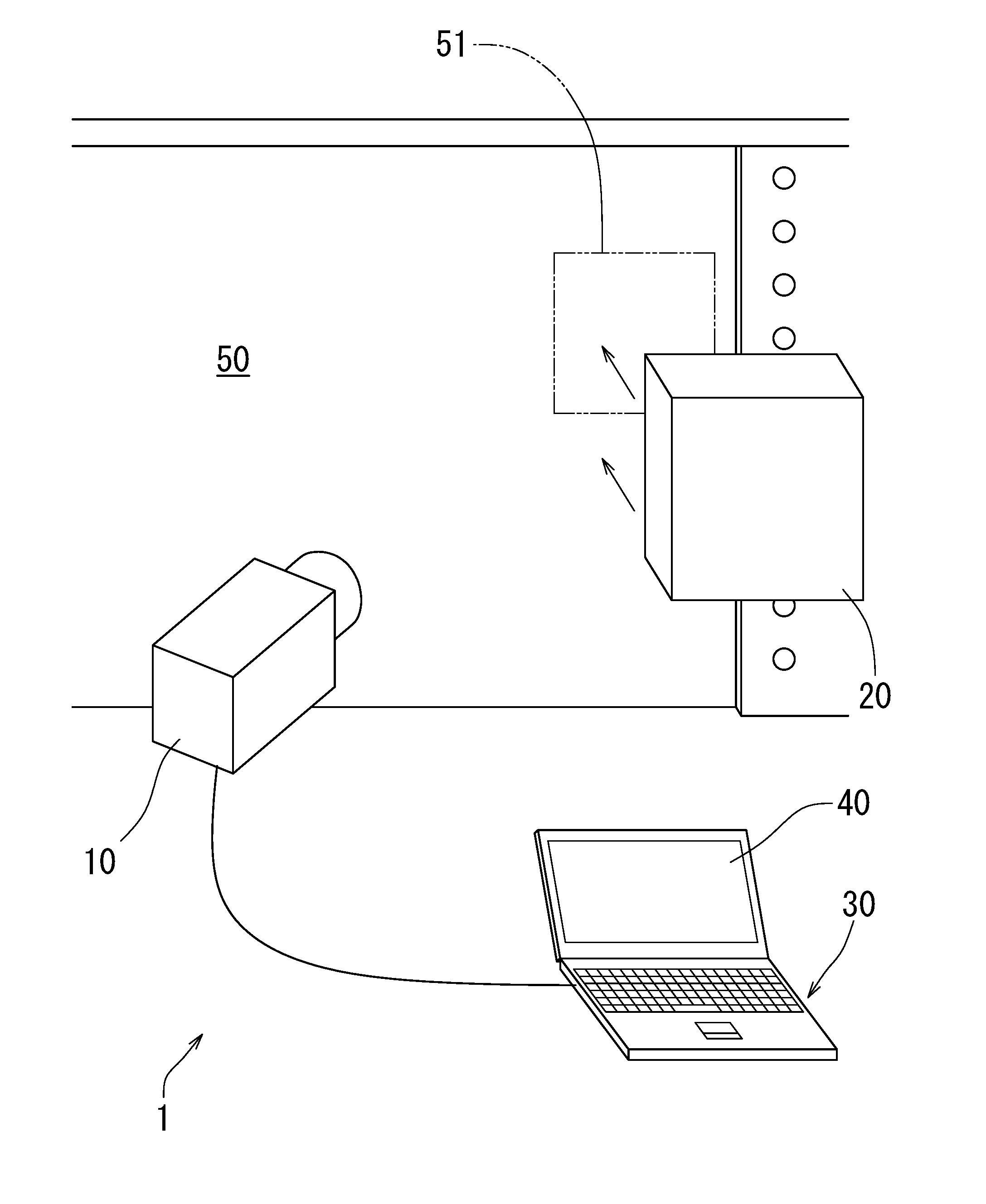
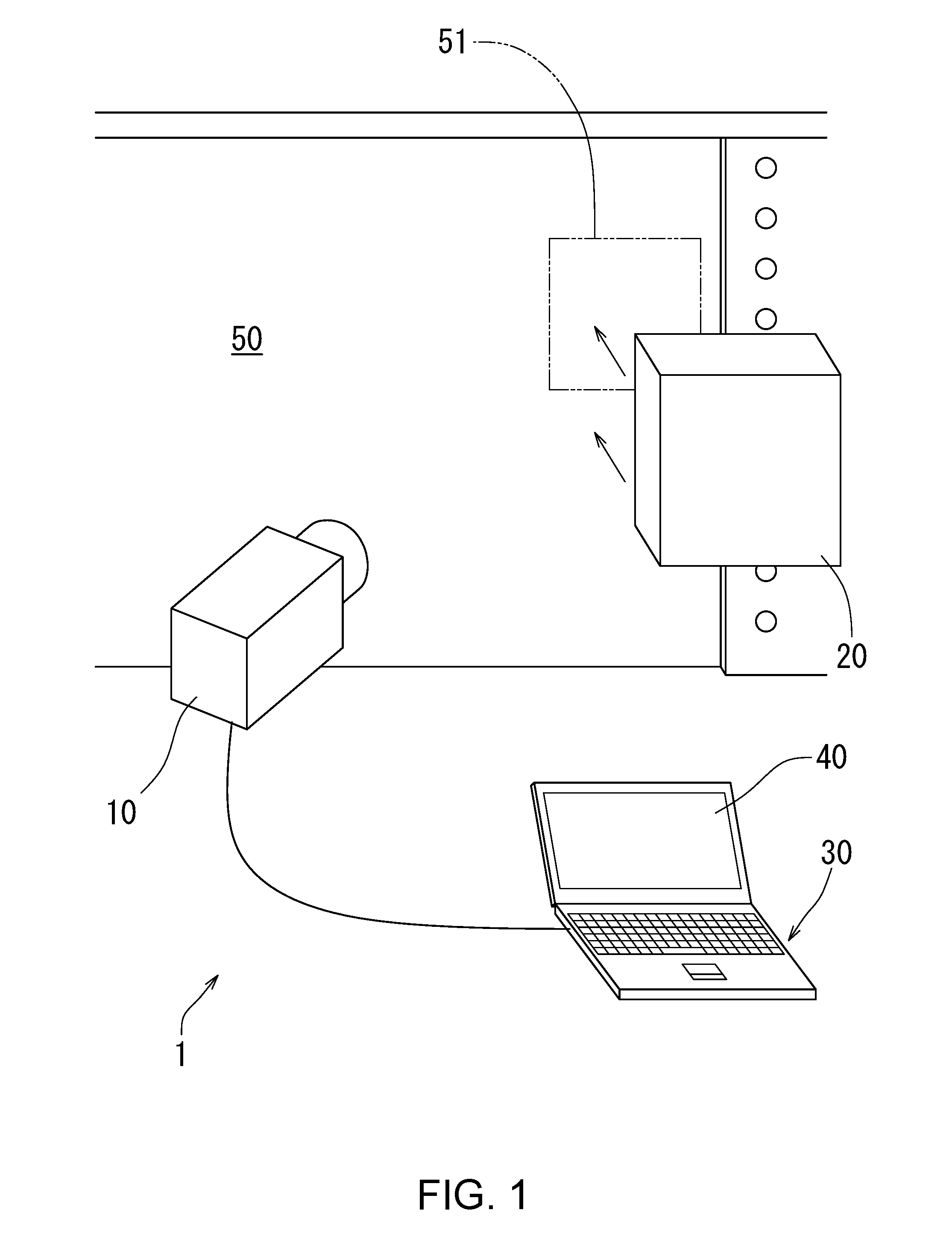
[0072]Now, a crack detection system according to the first embodiment of the present invention will be described below with reference to FIG. 1 to FIG. 3 as indicated above. The embodiment of the present invention will be described as an example in which a detection object is a structure such as a bridge or the like as made of steel and a part to be detected is a predetermined part of the steel covered with a coating layer (a coating film) applied by a coating method.

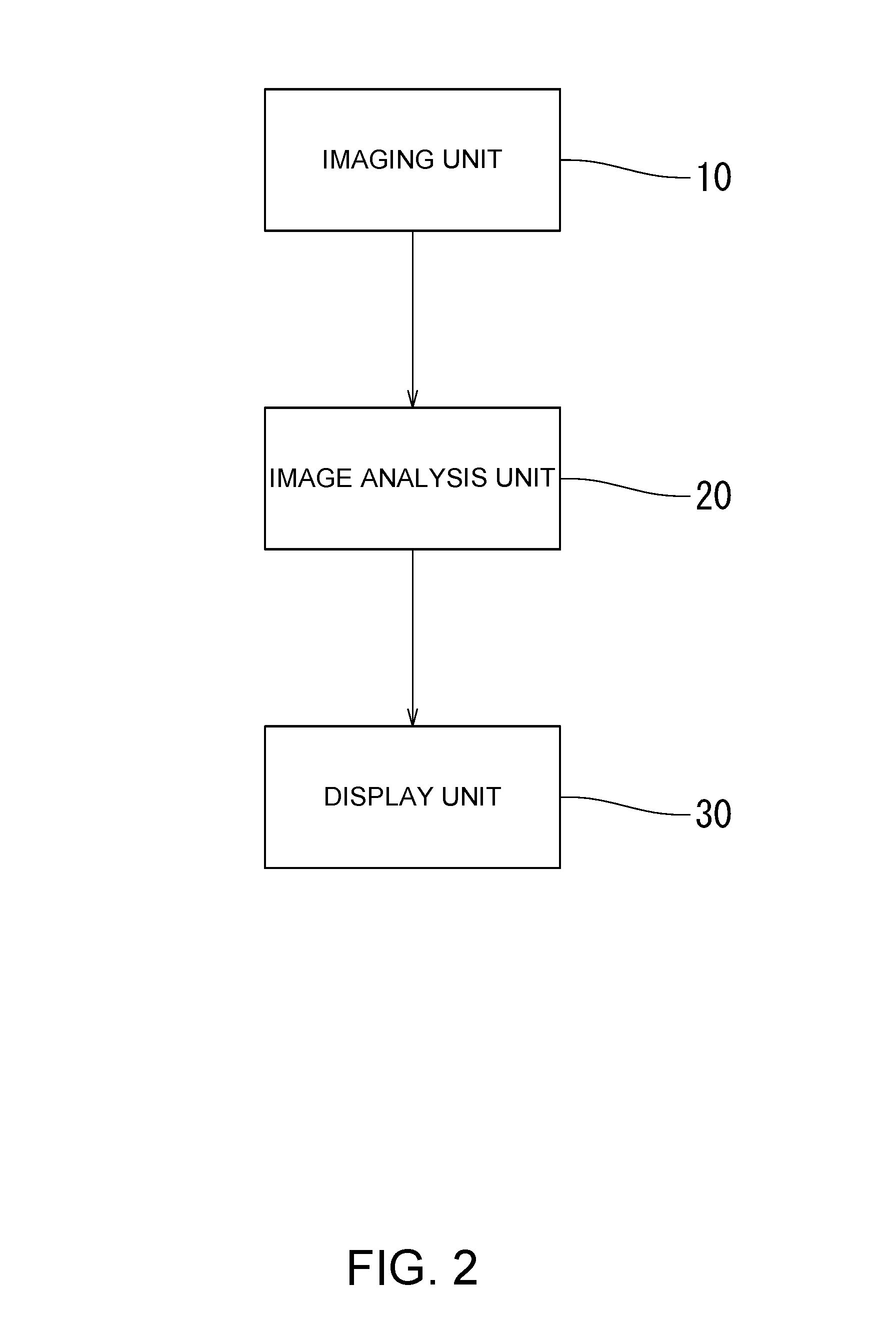
[0073]The crack detection system 1 utilizing a crack detection method according to the embodiment of the present invention as shown in each of these drawings comprises an imaging unit 10 that takes an image of the outermost coating surface of a predetermined part 51 to be detected, of a detection object 50, which is coated with a coating layer 53 from outside, a heating unit 20 that applies heat to the part 51 to be detected, by an induction heating, an image analysis unit 30 that analyzes two im...

second embodiment

of the Present Invention

[0110]The crack detection system according to the first embodiment of the present invention is configured in a way that the heating unit 20 applies the induction heating to the part 51 to be detected of the detection object 50, without limiting specifically any heating area. There may be an alternative configuration in which the heating unit 22 applies the induction heating with an alternating electric current having a sufficiently high frequency (for example, several dozen kHz) to the part 51 to be detected, to heat only the surface area, on the side near the heating unit, of the part 51 to be detected.

[0111]In this case, the heating unit 22 applies the alternating electric current having the predetermined frequency (for example, 20 kHz), by which only the surface area, on the side near the heating unit, of the part 51 to be detected can be heated through a skin effect by the eddy current, to provide a difference in temperature in the thickness direction of ...

third embodiment

of the Present Invention

[0117]The crack detection system according to the first embodiment of the present invention has been described as being configured that the detection of a crack can be achieved by using sequentially the imaging unit 10 and the heating unit 20, which are independent from each other. The present invention is not limited only to such an embodiment, and there may be applied another embodiment as the third embodiment of the present invention, in which an imaging unit 15 and a heating unit 25 are combined together into a united body so as to provide in use a single integrated device, which is movable relative to the detection object 50, as shown in FIG. 8.

[0118]In this case, the detection of a crack can be achieved while, sequentially shifting the respective part 51 to be detected of the detection object 50, i.e., the part whose image is to be taken by the imaging device 15 and to which part heat is applied. For example, if members for tracks 60 are placed along th...


PUM

PropertyMeasurementUnit
lengthaaaaaaaaaa
temperatureaaaaaaaaaa

Abstract

There is provided a crack detection system in which a crack can be detected from a strain distribution of a part to be detected of an object. After taking the image of the part to be detected of the detection object by the imaging unit, the heat is applied by the heating unit. Furthermore, image of the part to be detected are taken again and an image analysis unit analyzes the images before and after applying the heat to acquire a strain distribution of the part to be detected, so that the crack can be detected based on difference in a state of strain between a place where the crack exist and the other place. Therefore, taking the images of the part to be detected including its coating layer enables the analysis to progress without removing the coating layer to detect the crack.

Description

TECHNICAL FIELD[0001]The present invention relates to a crack detection method, which permits to confirm an existence of crack in a detection object in a non-destructive manner.BACKGROUND ART[0002]With respect to steel structures such as a bridge or the like, an appropriate maintenance work is required for these structures so that aged deterioration in load bearing ability and durability of such structures may not reduce the safety of them. Especially, under some circumstances where external forces are repeatedly applied to steel materials of the steel structure, for example, in a bridge to which a load is repeatedly applied along with the passage of vehicles, cracks may occur in places such as welded portions in which stress may easily concentrate, and such cracks may cause an event reducing the safety, such as fracture of the steel material, and accordingly, there is a strong demand to detect early the cracks.[0003]The major conventional ways to detect a crack caused in a steel ma...

Claims


Application Information

Patent Timeline
Patent Type & Authority Applications(United States)
IPC IPC(8): G01N21/956G01N21/88H05B6/02H05B6/36G01N25/72G01L5/00
CPCG01N21/956G01N25/72G01L5/00G01N2021/8893H05B6/36G01N21/8851H05B6/02
Inventor ITO, YUKIHIROSHIKI, KAZUHISAMATSUDA, HIROSHIDEMIZU, AKIRA
Owner SAGA UNIVERSITY
Why Eureka
Try Eureka