
Motor unit

a motor unit and motor technology, applied in the field of motor units, can solve the problems of increasing the noise such as surge current (voltage) in the plurality of semiconductor elements of the module, and achieve the effects of restrainting an increase in the size of the motor uni

Inactive Publication Date: 2016-09-01
JTEKT CORP
View PDF3 Cites 17 Cited by
  • Summary
  • Abstract
  • Description
  • Claims
  • Application Information

AI Technical Summary

Benefits of technology

The present invention provides a motor unit that can be restrained from increasing in size. By arranging electronic components on the control boards and along the shaft length direction of the motor shaft and on a plane that perpendicularly intersects with the extension line from the shaft end part of the motor shaft, the motor unit can be prevented from becoming larger. This helps to avoid unnecessary space and avoids wasting materials in the manufacturing process. By assigning functions to the control boards and optimizing space usage, the motor unit can be kept small in size. Overall, this invention ensures that the motor unit remains compact and efficient.

Problems solved by technology

In the wiring portion, as its length, that is, the supply passage for supplying the driving electric power to the motor is longer, an occurrence of noise such as surge current (voltage) in the plurality of semiconductor elements of the module is increased.

Method used


Image

  • Motor unit
  • Motor unit
  • Motor unit

Examples


Embodiment Construction

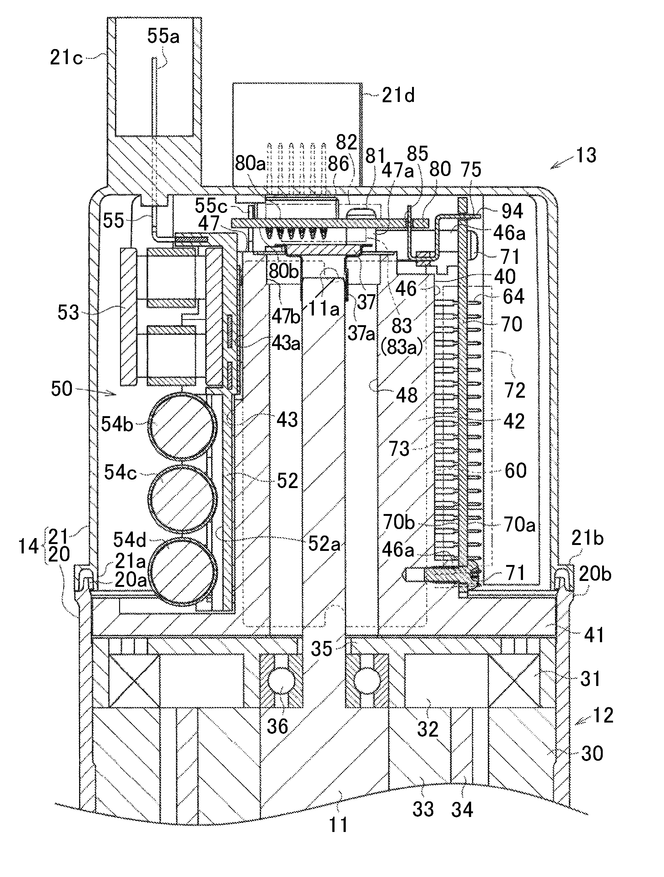
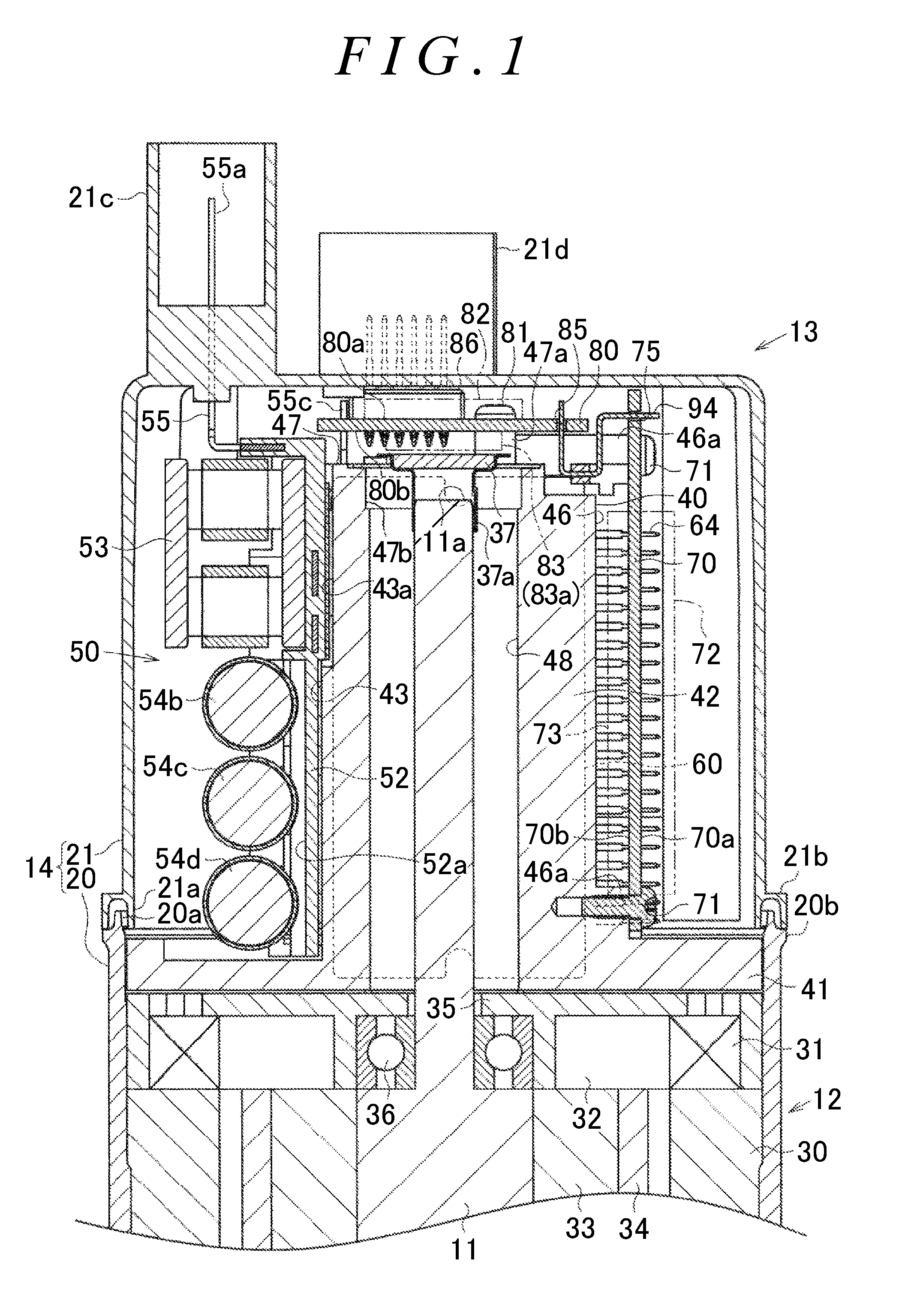
[0033]A motor unit according to an embodiment of the invention will be described below. As illustrated in FIG. 1, the motor unit includes a motor 12 that includes a rotatable motor shaft 11 and is operated when driving electric power is supplied to the motor 12, and a motor controller 13 that can execute a control to drive the motor 12. The motor 12 and the motor controller 13 are accommodated in a common motor housing 14 so as to be unitized. As will be described later, main constituents of the motor controller 13 include a wiring portion 50, a module 60, an operation control board 70, and a calculation control board 80. Note that the motor unit of the present embodiment is provided in an electric power steering apparatus of a vehicle, for example. The electric power steering apparatus controls the motor unit so as to generate an assist torque in accordance with a steering torque at the time when a driver of the vehicle operates a steering wheel.

[0034]As illustrated in FIG. 1, the ...


PUM


Abstract

A motor unit includes a motor; and a control board configured to execute a control to drive the motor. The control board includes a first control board and a second control board. The first control board is provided such that a mounting space for at least one electronic component perpendicularly intersects with an extension line extending from a shaft end part of a motor shaft and extends along a shaft radial direction so as to allow the at least one electronic component to be disposed along the shaft radial direction. The second control board is provided such that a mounting space for at least one electronic component extends along a shaft length direction so as to allow the at least one electronic component to be disposed along the shaft length direction. The motor and the control board are unitized.

Description

INCORPORATION BY REFERENCE[0001]The disclosure of Japanese Patent Applications No. 2015-039589 and 2015-039590 and 2015-039591 filed on Feb. 27, 2015 each including the specification, drawings and abstract is incorporated herein by reference in its entirety.BACKGROUND OF THE INVENTION[0002]1. Field of the Invention[0003]The present invention relates to a motor unit.[0004]2. Description of Related Art[0005]Conventionally, for example, a motor unit (a driving device) described in Japanese Patent Application Publication No. 2014-057514 (JP 2014-057514 A) is proposed as a motor unit in which a motor including a rotatable motor shaft and a control board configured to control and drive the motor by supplying driving electric power to the motor are unitized. In the motor unit of JP 2014-057514 A, members are arranged in order along a shaft length direction of the motor shaft in the motor. The members include the motor; a wiring portion serving as a supply passage for supplying driving elec...

Claims


Application Information

Patent Timeline
Patent Type & Authority Applications(United States)
IPC IPC(8): H02K11/33
CPCH02K11/33B62D5/0406H02K11/22
Inventor KOJIMA, YOSHIHIROKOIKE, SUSUMUTOYAMA, YUICHITANIKAWA, TAKAYAYAMASHITA, MANABU
Owner JTEKT CORP
Learn More