Sealed contact device

a contact device and sealing technology, applied in the direction of electromagnetic relays, electrical devices, electromagnetic relay details, etc., can solve the problems of deterioration of the magnetic characteristic of permanent magnets, inability to maintain efficient dissipation of arcs for a long period, etc., and achieve the effect of efficiently dissipating arcs

Active Publication Date: 2016-09-08
ORMON CORP
View PDF1 Cites 13 Cited by
  • Summary
  • Abstract
  • Description
  • Claims
  • Application Information

AI Technical Summary

Benefits of technology

[0021]According to one or more embodiments, it is possible to dissipate the a

Problems solved by technology

With the electromagnetic relay, however, the arc generated between the moving contacts 32 and the stationary contacts 34 impinges onto an inner peripheral surface of the container 26 so that the container 26 is damaged, and furthermor

Method used


Image

  • Sealed contact device
  • Sealed contact device
  • Sealed contact device

Examples


Embodiment Construction

[0038]One or more embodiments in which a sealed contact device according to the present invention is applied to a hermetically sealed electromagnetic relay will be described with reference to the accompanying drawings of FIGS. 1 to 12.

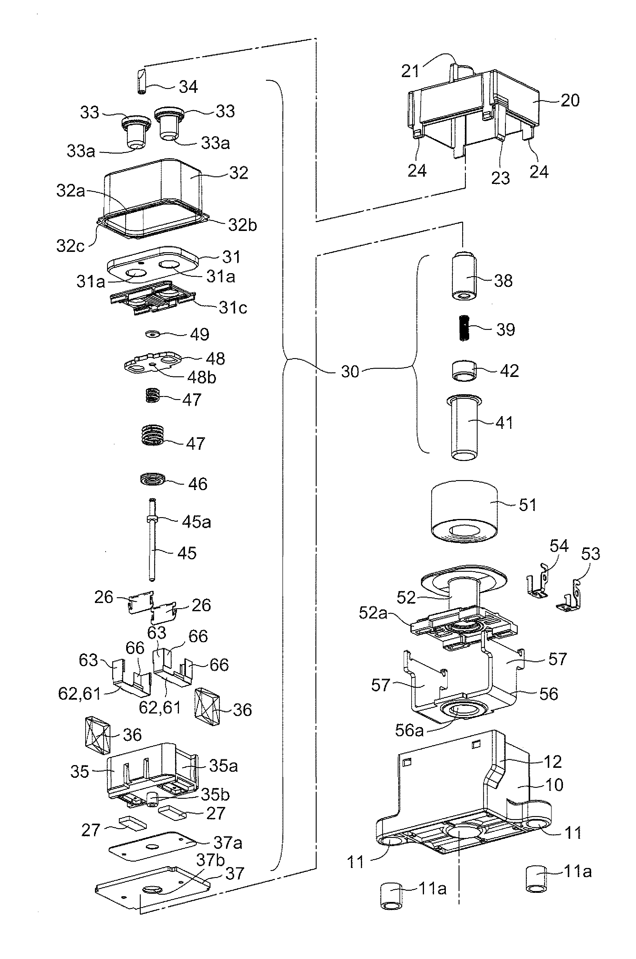
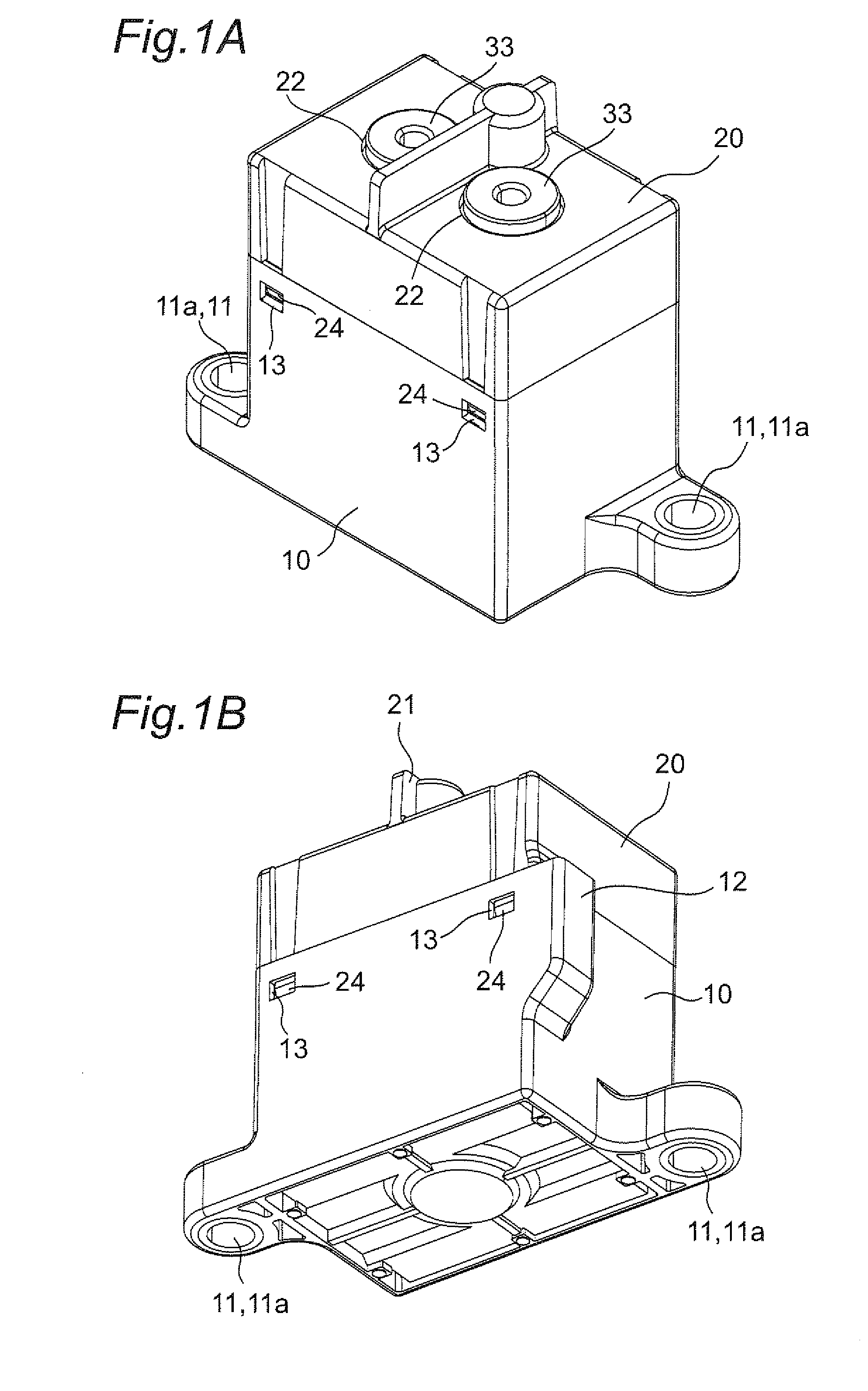
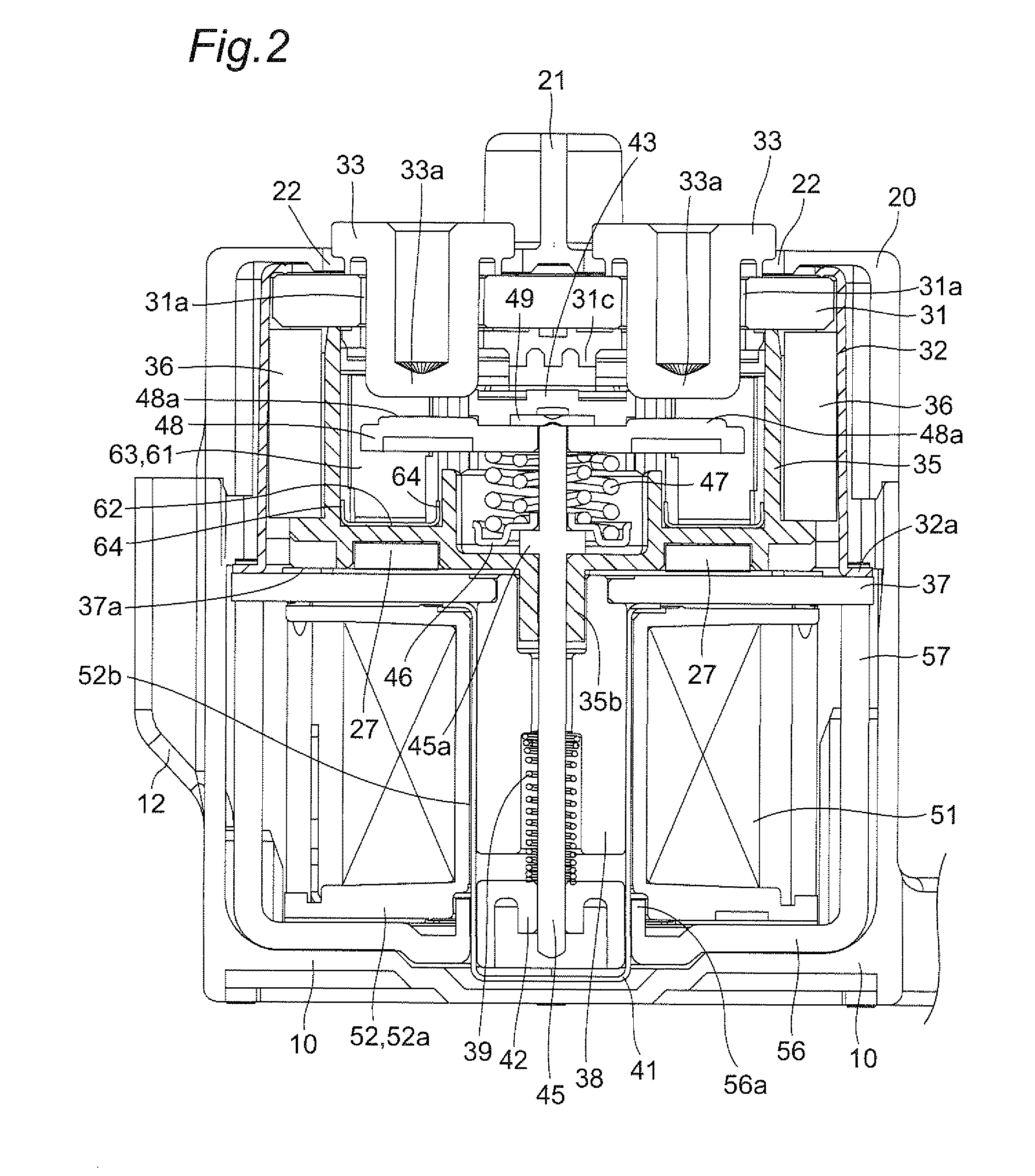
[0039]Referring to a sealing type electromagnetic relay according to one or more embodiments, as shown in FIGS. 1 to 10, particularly, FIGS. 6 and 7, a contact mechanism portion 30 and an electromagnet portion 50 for driving the contact mechanism portion 30 from an outside of a sealed space 43 are accommodated in a housing formed by assembling a cover 20 into a case 10. The contact mechanism portion 30 is assembled into the sealed space 43 including a ceramic plate 31, a metallic cylindrical flange 32, a plate-shaped first yoke 37 and a bottom-closed cylindrical member 41.

[0040]The case 10 is a resin molded product which is almost box-shaped. Also the case is provided on an outside surface at lower corner parts with attaching holes 11 each having mount...


PUM


Abstract

A sealed contact device capable of maintaining a function for drawing a generated arc to disappear rapidly and reliably for a long period. An electromagnetic relay includes a housing, a stationary contact and a moving contact which are disposed opposite to each other in the housing, and a pair of permanent magnets and disposed opposite to the stationary contact and the moving contact. An arc generated between the stationary contact and the moving contact is drawn due to a current conducting between the stationary contact and the moving contact and magnetic forces of the permanent magnets. An arc shield member is disposed in a position in which an arc in the housing is induced.

Description

TECHNICAL FIELD[0001]One or more embodiments of the present invention relate to a sealed contact device and more particularly to a power loading electromagnetic relay capable of dissipating a generated arc rapidly.BACKGROUND ART[0002]As a sealed contact device, conventionally, there is disclosed a hermetically sealed electromagnetic relay in which a moving shaft 44 to be reciprocated in an axial center direction based on magnetization and demagnetization of a solenoid 20 reciprocates a contact delivering member 28 having a pair of moving contacts 32 and 32 mounted thereon, thereby causing the moving contacts 32 to connect / disconnect from a stationary contact 34 (see Patent Document 1).[0003]Referring to the hermetically sealed electromagnetic relay, a pair of permanent magnets 30 is disposed on an outer peripheral surface of a resin container 26 in order to induce an arc generated between the moving contact 32 and the stationary contacts 34.PRIOR ART DOCUMENTSPatent Documents[0004]P...

Claims


Application Information

Patent Timeline
IPC IPC(8): H01H50/38H01H50/02H01H50/54
CPCH01H50/38H01H50/023H01H50/54H01H9/443H01H50/546H01H51/29
Inventor SHIMA, HIROMIMORI, MASAKIOKAMOTO, TAKUMA
Owner ORMON CORP
Why Eureka
Try Eureka