Acoustic wave element, filter element, and communication device

Active Publication Date: 2016-09-08
KYOCERA CORP
View PDF11 Cites 17 Cited by
  • Summary
  • Abstract
  • Description
  • Claims
  • Application Information

AI Technical Summary

Benefits of technology

[0009]According to the acoustic wave element of the present invention and the filter element provided with the same, a reduction of insertion loss or improvement of steepness of the passband can be achieved and the filter characteristi

Problems solved by technology

, it was difficult to satisfy the transmittance property and atte

Method used


Image

  • Acoustic wave element, filter element, and communication device
  • Acoustic wave element, filter element, and communication device
  • Acoustic wave element, filter element, and communication device

Examples


Embodiment Construction

[0035]Below, an acoustic wave (SAW: surface acoustic wave) element according to an embodiment of the present invention will be explained with reference to the drawings. Note that, the diagrams used in the following explanation are schematic ones. Proportions etc. on the drawings do not always match the actual ones.

[0036]In an acoustic wave element (below, also referred to as a “SAW element”), any direction may be defined as upward or downward. In the following description, for convenience, an orthogonal coordinate system xyz will be defined, and an “upper surface”, “lower surface”, and other terms will be used where the positive side in the z-direction is the upper part.

(Summary of Configuration of SAW Element)

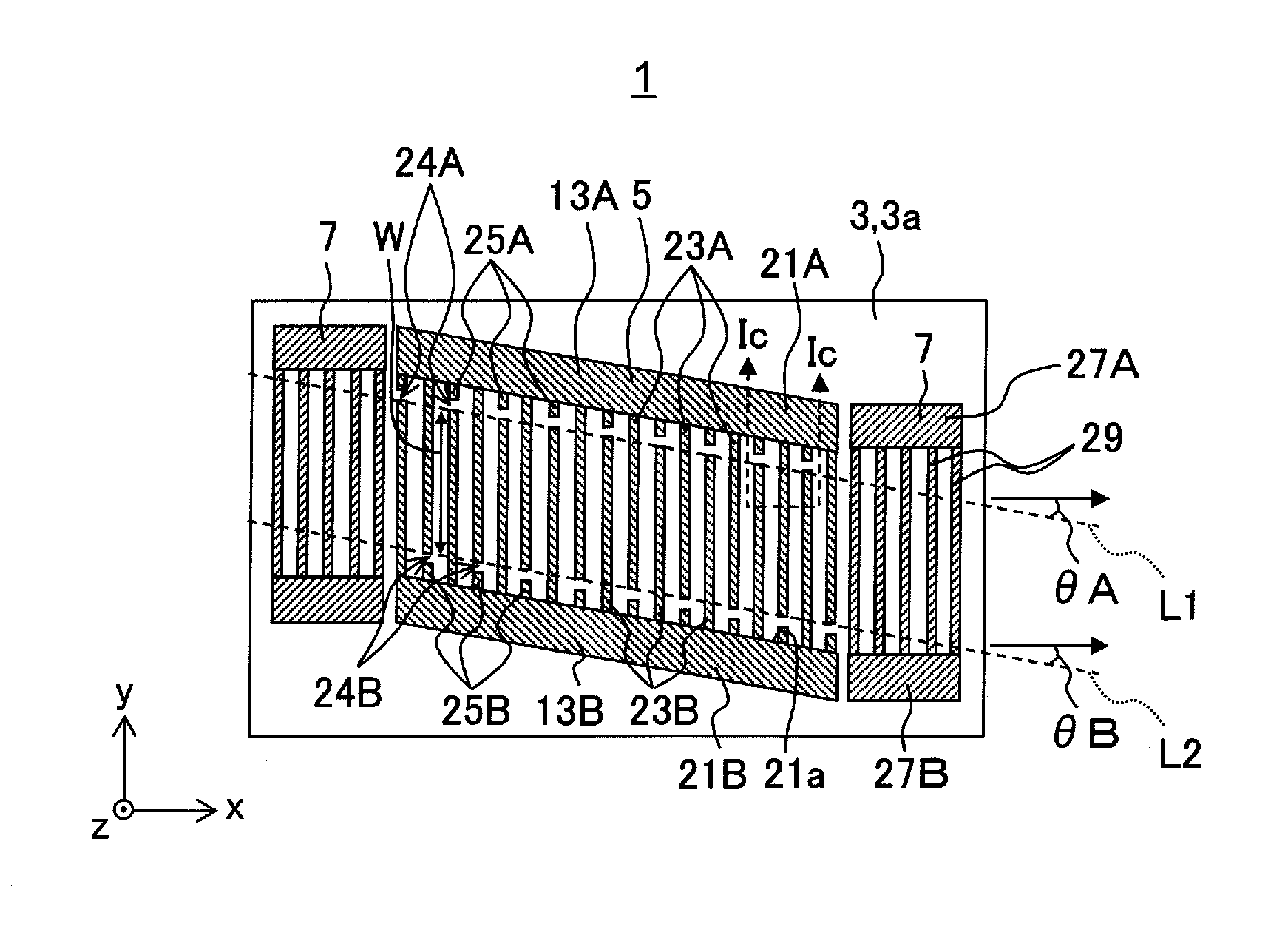
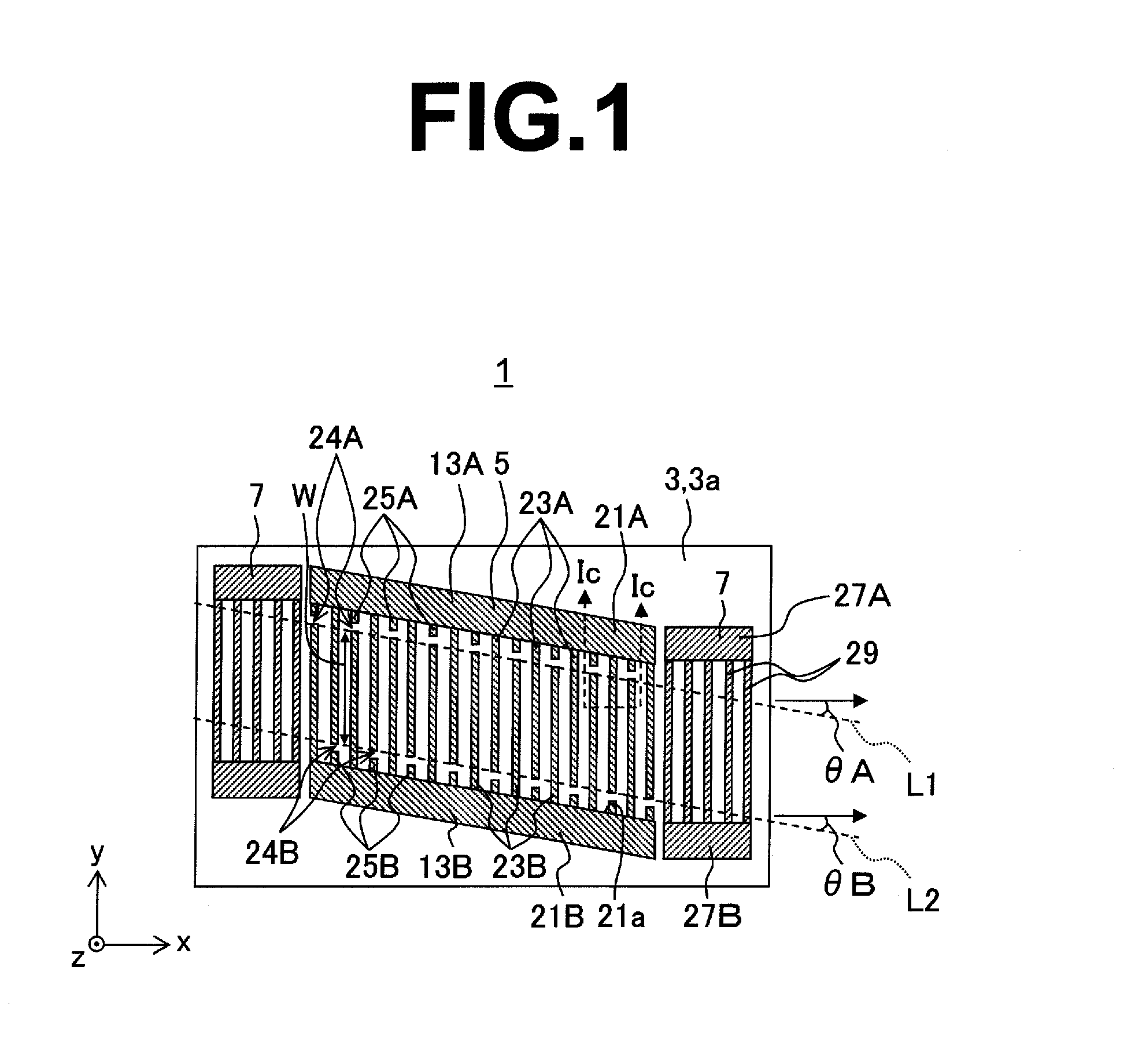
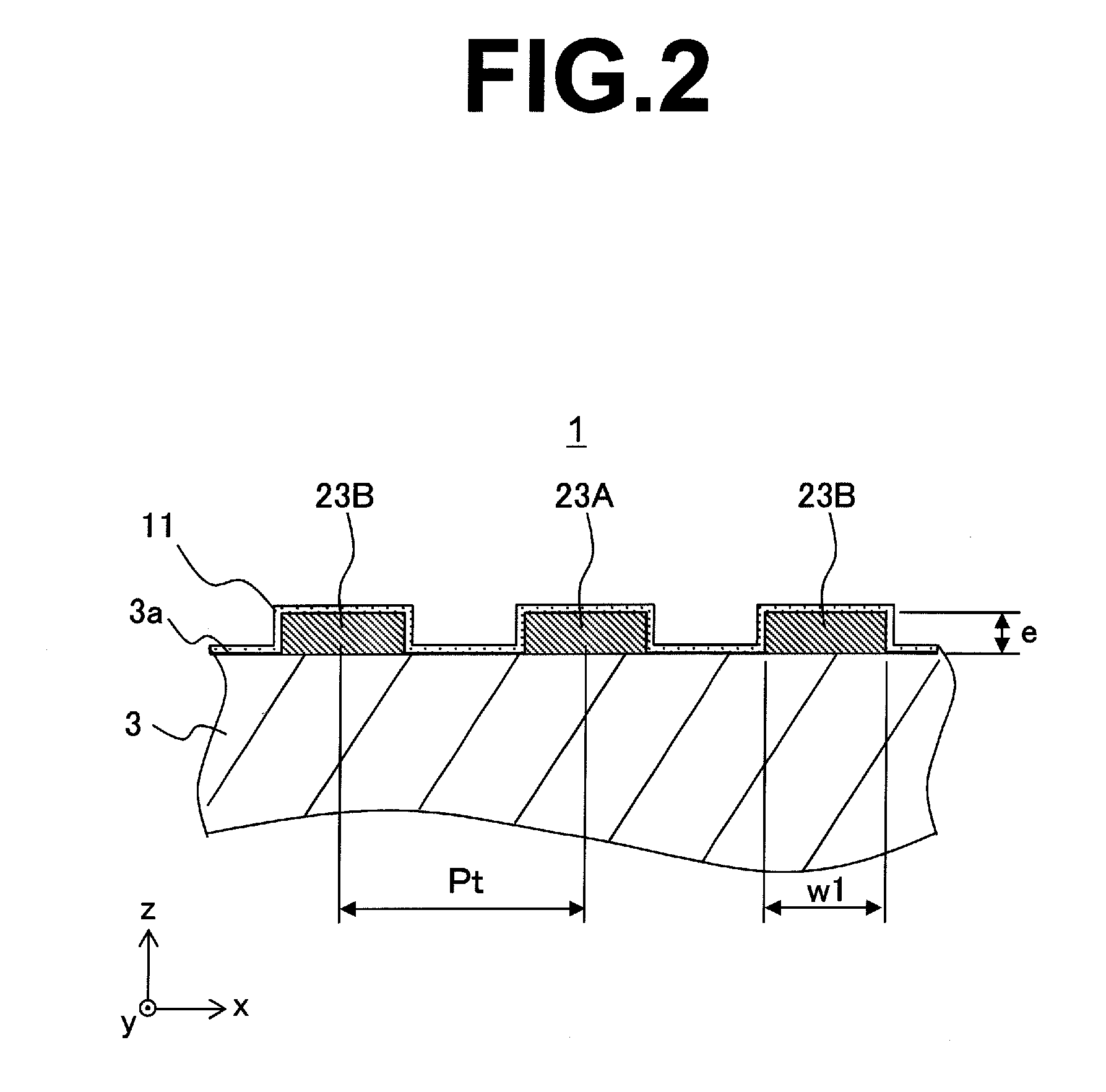
[0037]FIG. 1 is a plan view showing the configuration of a SAW element 1 according to an embodiment of the present invention. FIG. 2 is a cross-sectional view taken along the Ic-Ic line in FIG. 1.

[0038]The SAW element 1, as shown in FIG. 1, has a substrate 3, an excitation (ID...


PUM


Abstract

In an acoustic wave element of the present invention, a first imaginary line connecting end portions of the plurality of first electrode fingers in the IDT electrode on the second bus bar side and a second imaginary line connecting end portions of the plurality of second electrode fingers in the IDT electrode on the first bus bar side are within ranges of 2 degrees<θA≦10 degrees and 2 degrees<θB≦10 degrees where an angle formed by the first imaginary line and the propagation direction is the first inclination angle θA and an angle formed by the second imaginary line and the propagation direction is the second inclination angle θB.

Description

TECHNICAL FIELD[0001]The present invention relates to an acoustic wave element, filter element, and communication device.BACKGROUND ART[0002]Known in the art is an acoustic wave element having a piezoelectric substrate and an excitation electrode provided on the major surface of the piezoelectric substrate. Such an acoustic wave element is for example utilized for a reception filter (Rx filter) or transmission filter (Tx filter) of a branching filter.[0003]Here, in the branching filter, when the interval between the Tx band and the Rx band is narrow, since the frequency ends up moving due to a change of the ambient temperature (−30° C. to +85° C.), it was difficult to satisfy the transmittance property and attenuation property which are required for the Tx band and Rx band. As a technique for solving this, there is the technique of using a temperature-compensated piezoelectric substrate (see Japanese Patent Publication No. 2007-214902A etc.)SUMMARY OF INVENTIONTechnical Problem[0004...

Claims


Application Information

Patent Timeline
IPC IPC(8): H01Q1/52H03H9/64H03H9/56H03H9/25H03H9/17
CPCH01Q1/52H03H9/25H03H9/64H03H9/56H03H9/17H03H9/14594H03H9/02559H03H9/02834H03H9/1071H03H9/14547H03H9/6456H03H9/6483H03H9/725
Inventor TANAKA, HIROYUKI
Owner KYOCERA CORP
Why Eureka
Try Eureka