Pupillometers and systems and methods for using a pupillometer

a pupillometer and system technology, applied in the field of pupillometers and systems and methods for visual field testing, can solve the problems of not repeatability, especially severe problems, false medical diagnosis, etc., and achieve the effect of overcoming background deficiencies, being more reliable and repetitiv

Active Publication Date: 2016-09-15
TEL HASHOMER MEDICAL RES INFRASTRUCTURE & SERVICES
View PDF1 Cites 32 Cited by
  • Summary
  • Abstract
  • Description
  • Claims
  • Application Information

AI Technical Summary

Benefits of technology

[0010]There is an unmet need for a system and a method for objective chromatic perimetry analysis using a pupillometer that is adept at providing an indication of the state of health of the eye and in particular identifying damage to the eye. The present invention overcomes the deficiencies of the background by providing a system and method that provides an objective test and analysis that is able to quantify an individual's state of health of the eye. The system and method overcome the deficiencies of the art by providing individual specific indication of problem areas of the eye in obtaining measurements that are relative to an individual's field of vision at specific visual field testing points, rather than the full field test provided by the prior art. Moreover the objective test of optional embodiments of the present invention provides for a quick test that does not require patient specific interaction or input that is subjective and often unreliable or misleading. Rather, the test of the present invention most preferably measures a subject's PLR without a subject's input ensuring the objective nature of the test, hence more reliable and repetitive.

Problems solved by technology

The principal stumbling block of the above procedure is its subjectivity, requiring the patient to understand the testing instructions, fully cooperate, and complete the entire test in order to provide useful information.
However, the patient cooperation may strongly depend on his or her level of fatigue, wakefulness and attentiveness.
This problem is especially severe in case of ill or elderly patients, younger children or patients with mental disabilities and developmental delay.
Consequently, the test results obtained by the current method may not be accurate and may lead to false medical diagnosis.
Moreover, the results may not be repeatable, which does not allow for reliable and effective tracking of the patient's medical condition.
The pupillary response to spatially-localized luminance increments has been used as an indicator of glaucomatous retinal damage, but the small-area stimuli used in pupil perimetry may target small retinal areas that only weakly stimulate a PLR, and may fail to stimulate a PLR if the small retinal area that is being stimulated by light has been damaged by glaucoma.
Standard pupil perimetry testing produces large variations in pupil response amplitude among patients, and the changes in sensitivity of the pupil response with the retinal location of the small-area light stimulus have also limited the usefulness of such measurements.
However, these methods fail to achieve either accurate or repeatable visual field mapping due to their susceptibility to time variations in the human ocular system and to differences in the behavior of the ocular system of different patients.

Method used


Image

  • Pupillometers and systems and methods for using a pupillometer
  • Pupillometers and systems and methods for using a pupillometer
  • Pupillometers and systems and methods for using a pupillometer

Examples


example 1

Normal Subjects

[0183]The system and method described in FIGS. 1-3 was tested on subjects having a healthy eye. In total 25 eyes from 14 subjects were tested, 6 females and 8 males, with a mean age 29.8 years. The stimulus provided was as follows: the first stimulus characteristics were a chromatic beam having a wavelength of 480±19 nm, duration of about 1 s (one second), provided three times; inter-stimuli delay of 1023 ms (milliseconds) and intensity of 3.98×10⁻⁸ cd / m; and the second stimulus characteristics were a chromatic beam having a wavelength of 640±10 nm, duration of about 1 s (one second); inter-stimuli delay of 891 ms (milliseconds) and intensity of 3.98×10⁻⁸ cd / m2.

[0184]The visual field map was generated for both first and second stimuli,

[0185]FIG. 4 A shows the objective PLR response obtained with the second stimuli, while FIG. 4B shows the objective PLR response obtained with the first stimuli. Both FIGS. 4A and 4B show the respective population percentile score in 75t...

example 2

Retinitis Pigmentosa Subjects

[0188]The system and method described in FIGS. 1-3 was tested on subjects with diagnosed Retinitis Pigmentosa (“RP”). In total 17 eyes were tested from 11 subjects, 4 female and 7 male, with a mean age of 34.3 years. The stimulus tested was as follows: the first stimulus characteristics were a chromatic beam having a wavelength of 480±19 nm, duration of about 1 s (one second), provided three times; inter-stimuli delay of 1023 ms (milliseconds) and intensity of 3.98×10⁻⁸ cd / m2; and the second stimulus characteristics were a chromatic beam having a wavelength of 640±10 nm, duration of about 1 s (one second); inter-stimuli delay of 891 ms (milliseconds) and intensity of 3.98×10⁻⁸ cd / m2.

[0189]The visual field map was generated for both first and second stimuli in all subjects. An example taken from one subject is provided in FIGS. 5A-D. FIG. 5A shows the objective PLR response obtained with the second stimuli, while FIG. 5B shows the objective PLR response o...

example 3

Glaucoma Patient

[0193]The system and method described in FIGS. 1-3 was tested on subjects with diagnosed Glaucoma. In total 5 eyes were tested from 3 subjects, 1 female and 2 male, with a mean age of 66.5 years. The stimulus tested was as follows: the first stimulus characteristics were a chromatic beam having a wavelength of 480±19 nm, duration of about 1 s (one second), provided three times; inter-stimuli delay of 1023 ms (milliseconds) and intensity of 3.98×10⁻⁸ cd / m; and the second stimulus characteristics were a chromatic beam having a wavelength of 640±10 nm, duration of about 1 s (one second); inter-stimuli delay of 891 ms (milliseconds) and intensity of 3.98×10⁻⁸ cd / m2.

[0194]The visual field map was generated for both first and second stimuli in all subjects. An example taken from one subject is provided in FIGS. 6A-D. FIG. 6A shows the objective PLR response obtained with the second stimuli, while FIG. 6B shows the objective PLR response obtained with the first stimuli. The...


PUM


Abstract

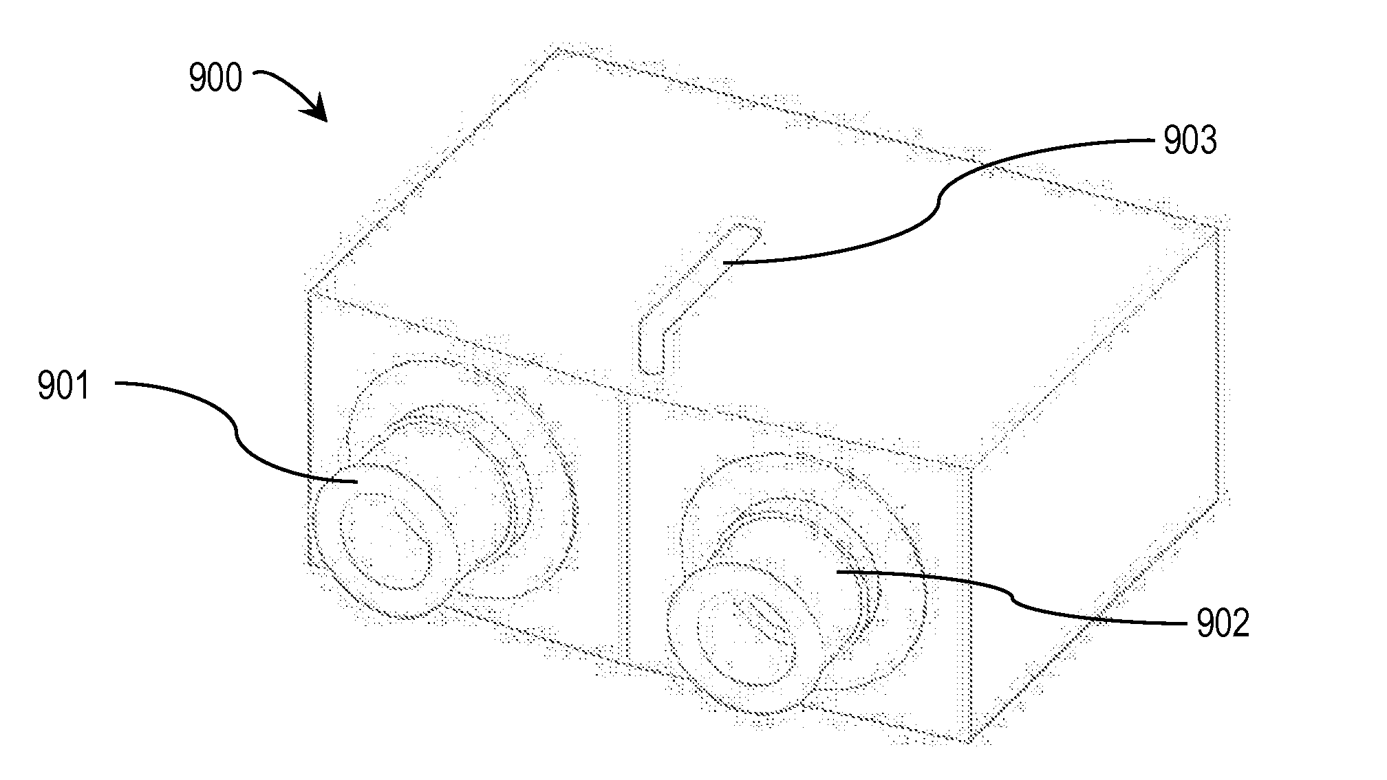
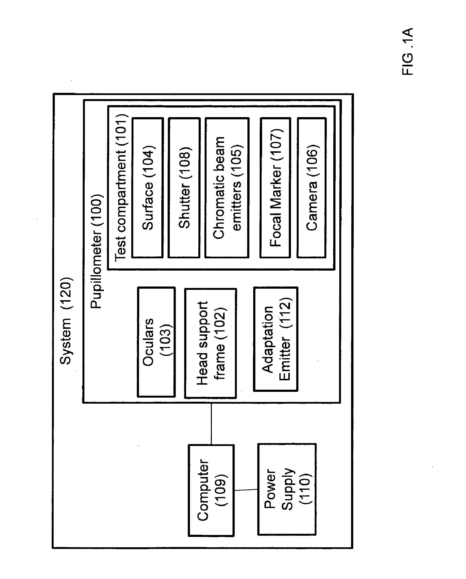
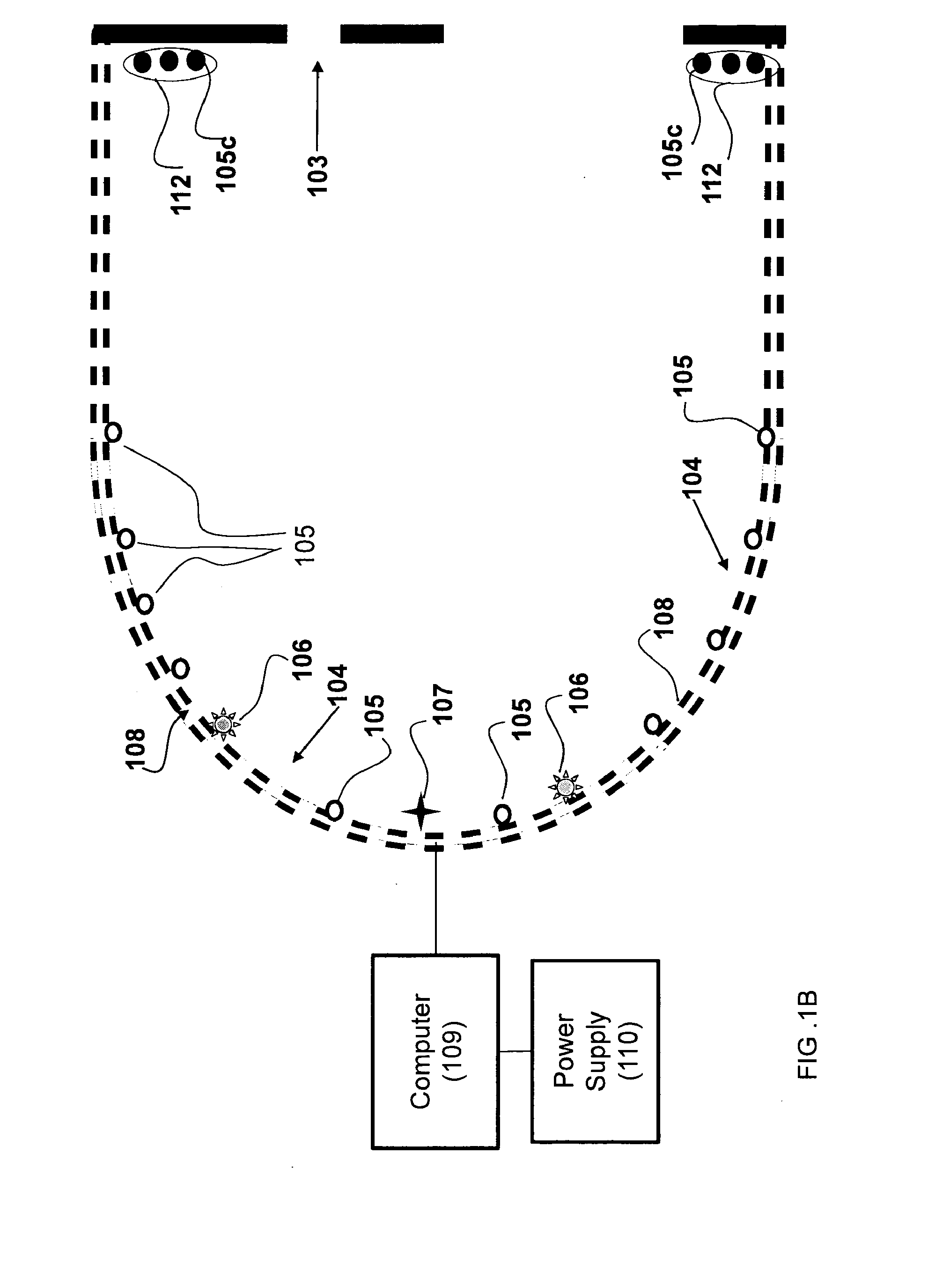
In one embodiment, a portable pupillometer including a testing compartment, at least one ocular disposed on the testing compartment, two or more light sources disposed in the testing compartment and forming a plurality of visual stimuli for a subject looking through the at least one ocular, at least one camera configured to capture images of a pupil of the subject via infrared detection, the images indicating pupillary responses to the two or more light sources, and an interface for connection with a computing device external to the pupillometer, the interface adapted to (i) provide, to the computing device, images from the at least one camera, and (ii) receive, from the computing device, control signals for controlling the plurality of light sources.

Description

FIELD OF THE INVENTION[0001]The present invention relates to systems, devices and methods for visual field testing and, in particular, to systems and methods for assessing various health conditions using a pupillometer.BACKGROUND OF THE INVENTION[0002]A visual field test, also known as perimetry, is a method of measuring an individual's entire scope of vision, that is, the central and peripheral vision. Such visual field tests attempt to map the visual field of each eye individually. Visual field testing is most frequently used to detect any signs of glaucoma-caused damage to the optic nerve. In addition it is useful for detection of central or peripheral retinal disease, eyelid conditions such as ptosis or drooping, optic nerve disease, and diseases affecting the visual pathways within the brain and associated with the Central Nervous System (“CNS”).[0003]The present prevailing method for visual field testing is performed as follows: one eye of the patient is covered, and the chin ...

Claims


Application Information

Patent Timeline
Patent Type & Authority Applications(United States)
IPC IPC(8): A61B3/11A61B3/14A61B3/00
CPCA61B3/112A61B3/0008A61B3/14A61B2560/0431A61B3/0075A61B3/0041A61B3/0025A61B3/0033A61B3/024
Inventor ROTENSTREICH, YGAL
Owner TEL HASHOMER MEDICAL RES INFRASTRUCTURE & SERVICES
Why Eureka
Try Eureka