Dot Recording Apparatus, Dot Recording Method, Computer Program Therefor, and Method of Manufacturing Recording Medium

a recording method and recording method technology, applied in the field of dots recording apparatus, can solve the problem of easy to spot color streaks, and achieve the effect of reducing memory requirements

Active Publication Date: 2016-09-15
SEIKO EPSON CORP
View PDF5 Cites 0 Cited by
  • Summary
  • Abstract
  • Description
  • Claims
  • Application Information

AI Technical Summary

Benefits of technology

[0010](4) In the recording apparatus of the aspect, the first concave polygon and the second concave polygon may hav...

Problems solved by technology

In JP-A-6-22106, there has been a problem that the color streaks can be easily noticeable because the length of a sub-scanning direction of each pixel group is a length of a sub-scanning direction in a region where the beginning portion of the hitting of dots in a first pass and the beginning portion of the hitting of dots in a second pass are adjacent to each other, and the length of a sub-scanning direction of each pixel gr...

Method used


Image

  • Dot Recording Apparatus, Dot Recording Method, Computer Program Therefor, and Method of Manufacturing Recording Medium
  • Dot Recording Apparatus, Dot Recording Method, Computer Program Therefor, and Method of Manufacturing Recording Medium
  • Dot Recording Apparatus, Dot Recording Method, Computer Program Therefor, and Method of Manufacturing Recording Medium

Examples


first embodiment

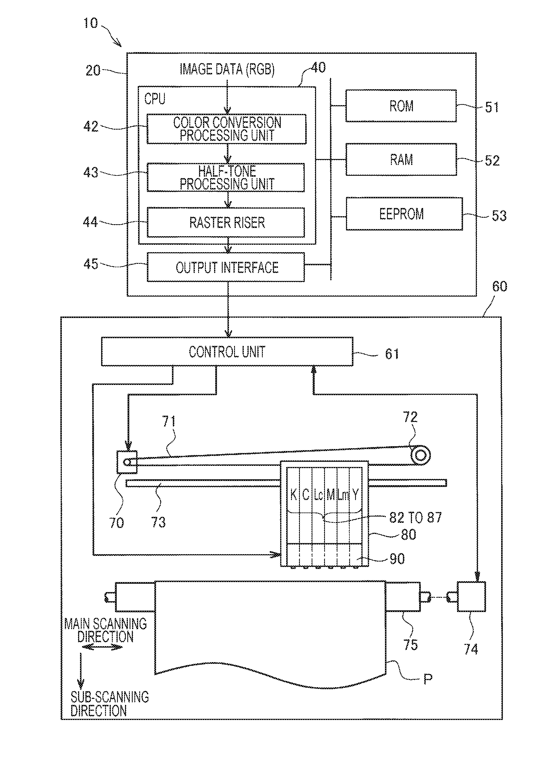
[0024]FIG. 1 is an explanatory view illustrating a configuration of a dot recording system 10. The dot recording system 10 includes an image processing unit 20 and a dot recording unit 60. The image processing unit 20 generates recording data for the dot recording unit 60 from image data (for example, image data of RGB).

[0025]The image processing unit 20 includes a CPU 40 (referred to as a “controller 40”), a ROM 51, a RAM 52, an EEPROM 53, and an output interface 45. The CPU 40 has functions of a color conversion processing unit 42, a half-tone processing unit 43, and a raster riser 44. These functions are realized by a computer program. The color conversion processing unit 42 converts multi-tone RGB data of image into ink amount data that represents the amount of ink in plural colors of ink. The half-tone processing unit 43 creates dot data that represents a dot formed state for every pixel by performing half-tone processing on the ink amount data. The raster riser 44 sorts the do...

second embodiment

[0044]FIGS. 7A to 7C are explanatory views illustrating a dot recording pattern and a mask for creating the dot recording pattern in a second embodiment. In the second embodiment, shapes of the supercell regions SC1 and SC2 are concave polygon shapes, and the second embodiment is different from the first embodiment in that dots are recorded in four passes (hereinafter, referred to as “four pass”) with respect to the first embodiment where dots are recorded in two passes (hereinafter, referred to as “two pass”).

[0045]FIG. 7A illustrates positions of a recording head 90 and regions that are recorded in each pass in the first pass to the fourth pass. Numbers illustrated in FIG. 7A represent an order of a pass, as 1 is the first pass and 2 is the second pass. In addition, regions recorded in the odd-numbered passes are hatched, and regions recorded in the even-numbered passes are not hatched. A part of regions Q1 to Q4 are recorded in the first pass, a part of regions Q2 to Q5 are recor...

third embodiment

[0053]FIGS. 9A to 9C are explanatory views illustrating a dot recording pattern and a mask for creating the dot recording pattern according to a third embodiment. The third embodiment uses a common mask used in the second embodiment, but is different from the second embodiment in that it is performed in the second pass. FIG. 9A illustrates positions of the nozzle array 95 and regions recorded in each pass from the first pass to the fourth pass. Numbers of FIG. 9A represent an order of passes, and regions recorded in the odd-numbered passes are hatched, and regions recorded in the even-numbered passes are not hatched. A part of regions Q1 and Q2 are recorded in the first pass, a part of regions Q2 and Q3 are recorded in the second pass, a part of regions Q3 and Q4 are recorded in the third pass, and a part of regions Q4 and Q5 are recorded in the fourth pass.

[0054]A shape of the mask M1 in the third embodiment has a shape in which dots of a recording start portion are added to a reco...


PUM


Abstract

A dot recording apparatus performs multi-pass recording through which recording of dots is terminated in main scanning passes of N times (N is an integer equal to or greater than two) on a main scanning line, the multi-pass recording is performed for respective supercell regions defined as a region including pixel positions on which recording of dots is performed in each main pass, a first supercell region recorded in a first pass in the supercell regions is configured with a first concave polygon having a concave portion and a convex portion, a second supercell region recorded in a second pass in the supercell regions is configured with a second concave polygon having a concave portion and a convex portion, and shapes of the first concave polygon and the second concave polygon are inversely symmetrical shapes in the main scanning direction.

Description

BACKGROUND[0001]1. Technical Field[0002]The invention relates to a dot recording apparatus, a dot recording method, a computer program therefor, and a method of manufacturing a recording medium.[0003]2. Related Art[0004]A recording apparatus that reciprocates a plurality of recording heads for discharging ink of different colors on a recording material, and performs recording by performing main scanning when reciprocating, has known as a dot recording apparatus (for example, JP-A-6-22106). In this recording apparatus, pixel groups configured with m×n pixels are arranged so as to be not adjacent to each other within a region on which images can be recorded by one main scanning. In addition, recording is completed by performing a plurality of times of the main scanning using a plurality of thinning patterns in complimentary sequence relationships with each other.[0005]In the beginning of recording of dots, dots are recorded in a state where there is no vibration of a recording head. H...

Claims


Application Information

Patent Timeline
IPC IPC(8): B41J2/21
CPCB41J2/2121G06K15/107B41J2/2132G06K15/105H04N1/047
Inventor YOSHIKAWA, EISHIN
Owner SEIKO EPSON CORP
Why Eureka
Try Eureka