Method for controlling gear shifting in a hybrid driveline by use of an electric machine

a hybrid driveline and electric machine technology, applied in mechanical equipment, gear shifting, transportation and packaging, etc., can solve the problems of shock wave, swinging, gap between components interacting in the transmission, and will be perceived as uncomfortable by the vehicle's driver and passengers, and achieve short shifting time and good driving comfor

Active Publication Date: 2016-09-15
SCANIA CV AB
View PDF3 Cites 11 Cited by
  • Summary
  • Abstract
  • Description
  • Claims
  • Application Information

AI Technical Summary

Benefits of technology

[0008]Despite prior art solutions, there is a need to further develop a hybrid powertrain, which provides good driving comfort in the vehicle during shifting, which has a short shifting time and which compensates for a poorly estimated contact point between the coupling parts of the coupling device at the connection of the combustion engine.
[0009]The objective of the present invention is thus to provide a hybrid powertrain, which provides good driving comfort in the vehicle during shifting.
[0010]Another objective of the invention is to provide a hybrid powertrain with a short shifting time.

Problems solved by technology

In the powertrain, there are gaps between the components interacting in the transmission, arising e.g. as a result of backlash among cogwheels in engagement.
In the event the electric machine is accelerated or decelerated after a second gear has been engaged, the gaps and resilient shafts will cause a pulse and a shock wave in the hybrid powertrain, which will be experienced as a disturbance by the driver and passengers in the vehicle.
This swinging will also be perceived as uncomfortable by the vehicle's driver and passengers.
After the second gear has been engaged and torque is supplied to the transmission, there is no guarantee that the combustion engine will be operated at the speed required for it to be connected and supply torque to the transmission.

Method used


Image

  • Method for controlling gear shifting in a hybrid driveline by use of an electric machine
  • Method for controlling gear shifting in a hybrid driveline by use of an electric machine
  • Method for controlling gear shifting in a hybrid driveline by use of an electric machine

Examples


Embodiment Construction

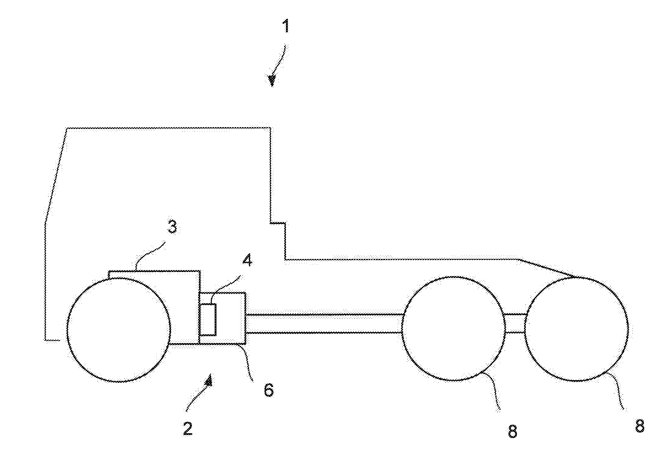
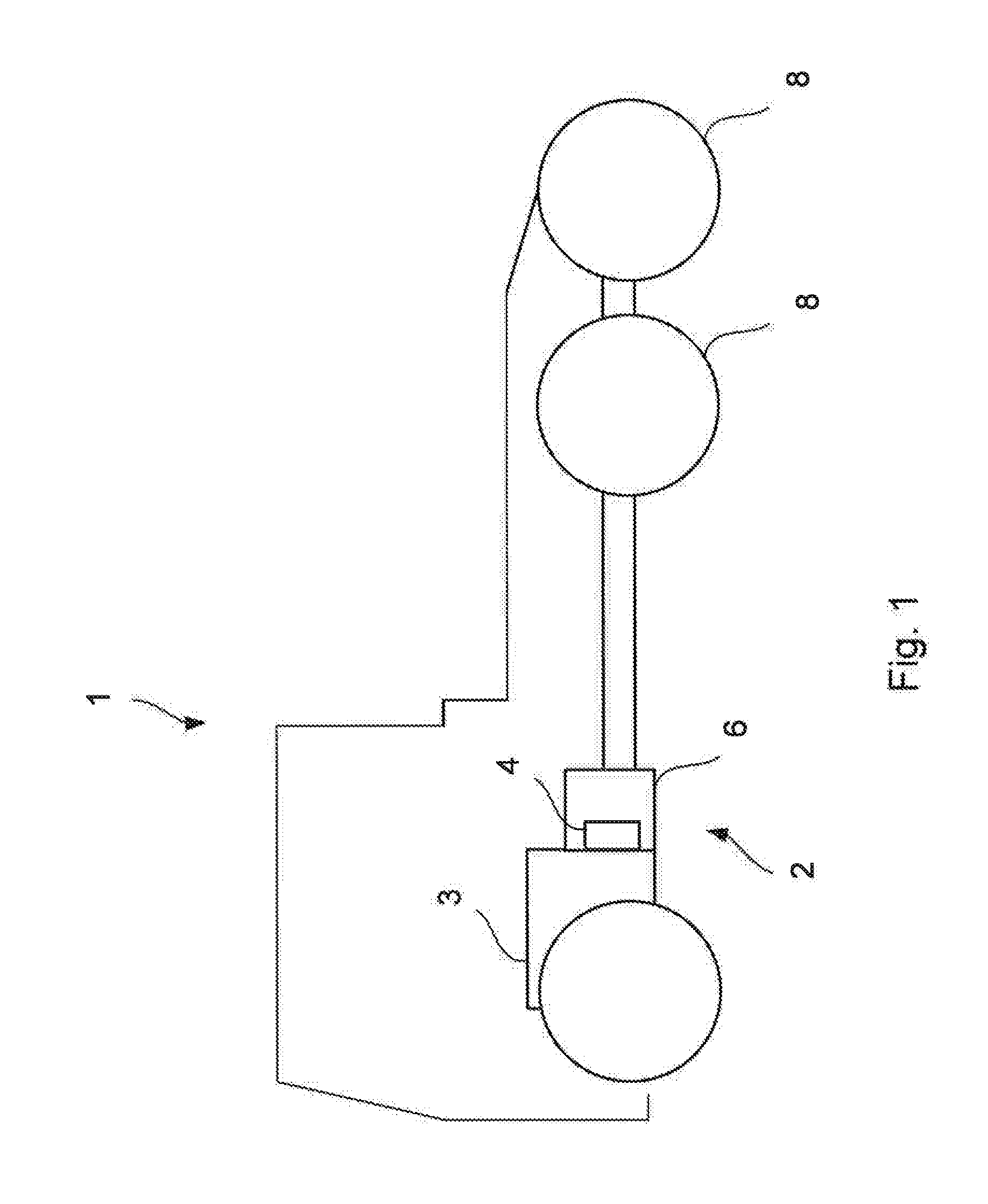
[0023]FIG. 1 shows a schematic side view of a vehicle 1, comprising a hybrid powertrain 2 with a combustion engine 3 and an electric machine 4, which are connected to a gearbox 6. The gearbox 6 is also connected to the driving wheels 8 of the vehicle 1.

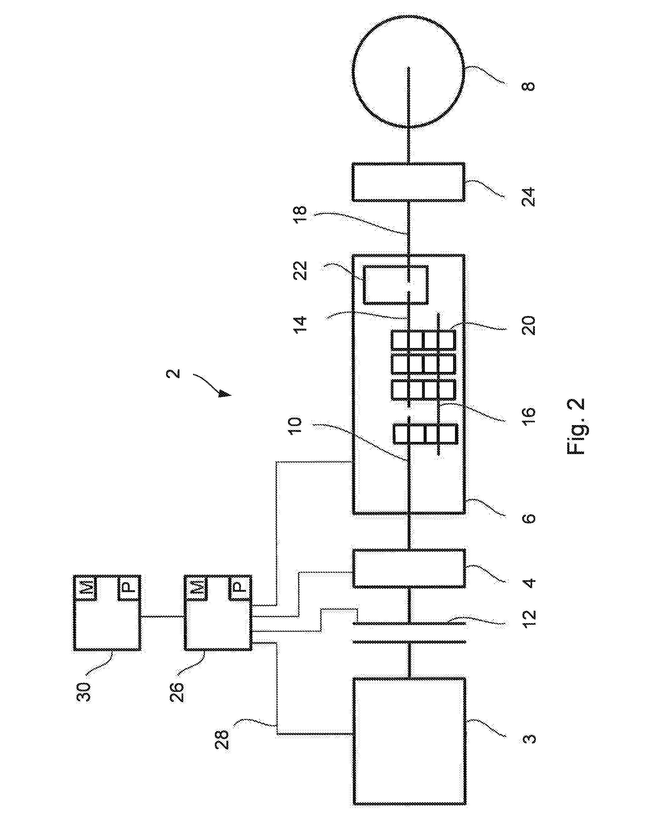
[0024]FIG. 2 shows a schematic view of a hybrid powertrain 2, comprising a combustion engine 3 and an electric machine 4, which are connected to an input shaft 10 of the gearbox 6. The combustion engine 3 may be connected to and disconnected from the input shaft 10 via a coupling device 12, which may be manually and / or automatically maneuverable. The gearbox 6 is preferably a combined manual and automatic gearbox 6 of split type and comprises a main shaft 14, a lay shaft 16, and an output shaft 18 on which one or several cogwheels 20 are arranged. Between the main shaft 14 and the output shaft 18, a retarder 22 is arranged. The output shaft 18 is connected to a final gear 24, which in turn is connected to the driving wheels 8 of the v...


PUM


Abstract

A method to control a hybrid powertrain (2) in a vehicle, the powertrain including a combustion engine (3), an electric machine (4) and a gearbox (6) with an input shaft (10) and output shaft (18), wherein the combustion engine (3) and the electric machine (4) are connected to the input shaft (10). The method includes the steps of controlling the gearbox (6) to a neutral position; controlling the speed of the electric machine (4) to a predetermined speed, corresponding to a target speed for the input shaft (10) according to the next selected gear; engaging a gear in the gearbox (6); controlling the electric machine (4), so that the electric machine (4) accelerates or decelerates depending on a requested driving torque for the vehicle (1); detecting when a control signal for the electric machine (4) corresponds to a predetermined signal value; and controlling the electric machine (4) to the requested driving torque. Also, a hybrid powertrain and a vehicle (1), and a computer program (P) and a computer program product for performing the method are disclosed.

Description

CROSS-REFERENCE TO RELATED APPLICATIONS[0001]The present application is a 35 U.S.C. §§371 national phase conversion of PCT / SE2014 / 051348, filed Nov. 13, 2014, which claims priority of Swedish Patent Application No. 1351381-7, filed Nov. 21, 2013, the contents of which are incorporated by reference herein. The PCT International Application was published in the English language.BACKGROUND OF THE INVENTION AND PRIOR ART[0002]The present invention relates to a method to control a hybrid powertrain in a vehicle, to a hybrid powertrain, which comprises elements to control the method, and also a vehicle, which comprises such a hybrid powertrain.[0003]Some trucks are equipped with a transmission of both an automatic and a manual type. With this type of transmission, shifting is carried out from a first gear to a second gear by bringing the gearbox from one torque state in the powertrain to a substantially zero torque state, subsequently disengaging the current gear, and subsequently synchro...

Claims


Application Information

Patent Timeline
Patent Type & Authority Applications(United States)
IPC IPC(8): B60W20/30B60W10/08B60W10/06B60K6/547B60W20/10B60W20/40B60K6/36B60K6/40B60W10/02B60W10/11
CPCB60W20/30B60Y2300/19B60W10/08B60W10/06B60W10/11B60W20/10B60W20/40B60K6/36B60K6/40B60K6/547B60W2510/083B60W2540/10B60W2710/1005B60W2710/021B60W2710/0666B60W2710/081B60W2710/082B60W2710/083Y10S903/909Y10S903/951Y10S903/919Y10S903/93B60Y2200/92B60Y2300/188B60W10/02B60K6/48B60W30/18F16H3/12F16H2061/0422F16H2063/506F16H3/126B60K6/387B60K2006/4825B60W2300/12B60W2510/1005B60W30/19B60W20/00B60W2510/1015B60W2510/104B60W2710/1011Y02T10/62B60W30/188B60W2710/1038F16H3/091F16H61/0403F16H61/0437
Inventor NILSSON, MATTIASSUNDEN, FREDRIKLIWELL, MATSKOURIE, AFRAM
Owner SCANIA CV AB
Why Eureka
Try Eureka