
Power working machine

a working machine and working belt technology, applied in the direction of combustion engines, fuel air cleaners, charge feed systems, etc., can solve the problems of deteriorating the performance of internal combustion engines, abnormal conditions, and sand-like dust that includes sawdust, and suppress the deterioration of centrifugal separation functions. , the effect of suppressing the generation of swirling current near the air intake por

Inactive Publication Date: 2016-09-15
YAMABIKO CORP
View PDF11 Cites 3 Cited by
  • Summary
  • Abstract
  • Description
  • Claims
  • Application Information

AI Technical Summary

Benefits of technology

The present invention aims to provide a portable power working machine that can prevent dust from entering the air intake system of an air-cooled internal combustion engine, reduce the likelihood of clogging an air cleaner, and eliminate the need for frequent cleaning. This is achieved by creating an air intake port that prevents dust from flowing into the air intake system and directs clean air towards the engine in a more efficient manner.

Problems solved by technology

In the operation of the portable power working machine as described above, dust that includes sawdust, powder of cut material and sand-like dust is inevitably generated.
When dust of those kinds is allowed to be sucked together with air into the air intake system of the internal combustion engine and to collect on the filter element of the air cleaner, clogging of the filter occurs, thus giving rise to abnormal conditions and deterioration of the performance of the internal combustion engine due to insufficiency in the intake air amount.
Accordingly, it is required in the operation of the portable power working machine to frequently clean the air cleaner and the like, which is a task that is quite troublesome for the operator.

Method used


Image

  • Power working machine
  • Power working machine
  • Power working machine

Examples


Embodiment Construction

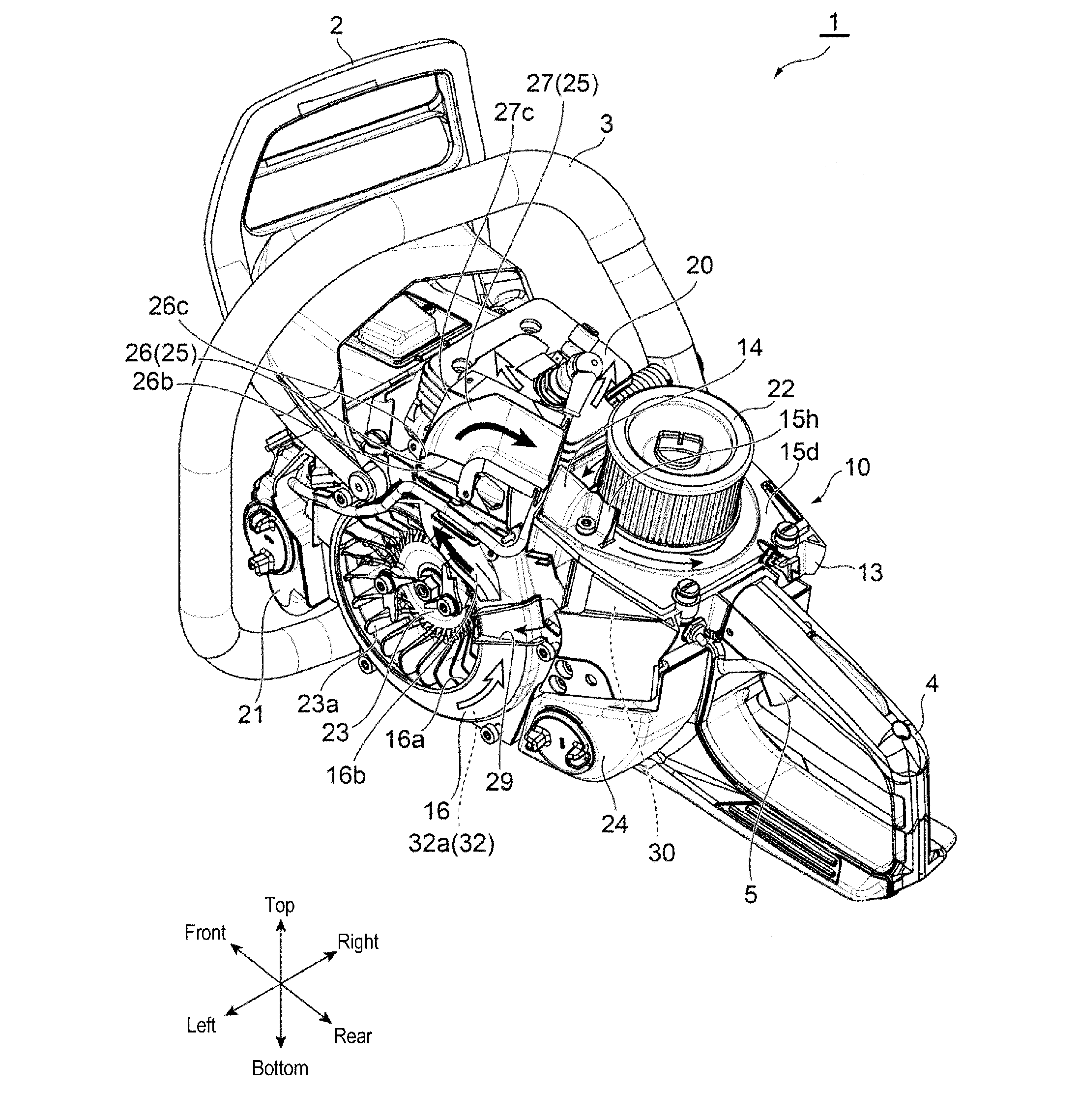
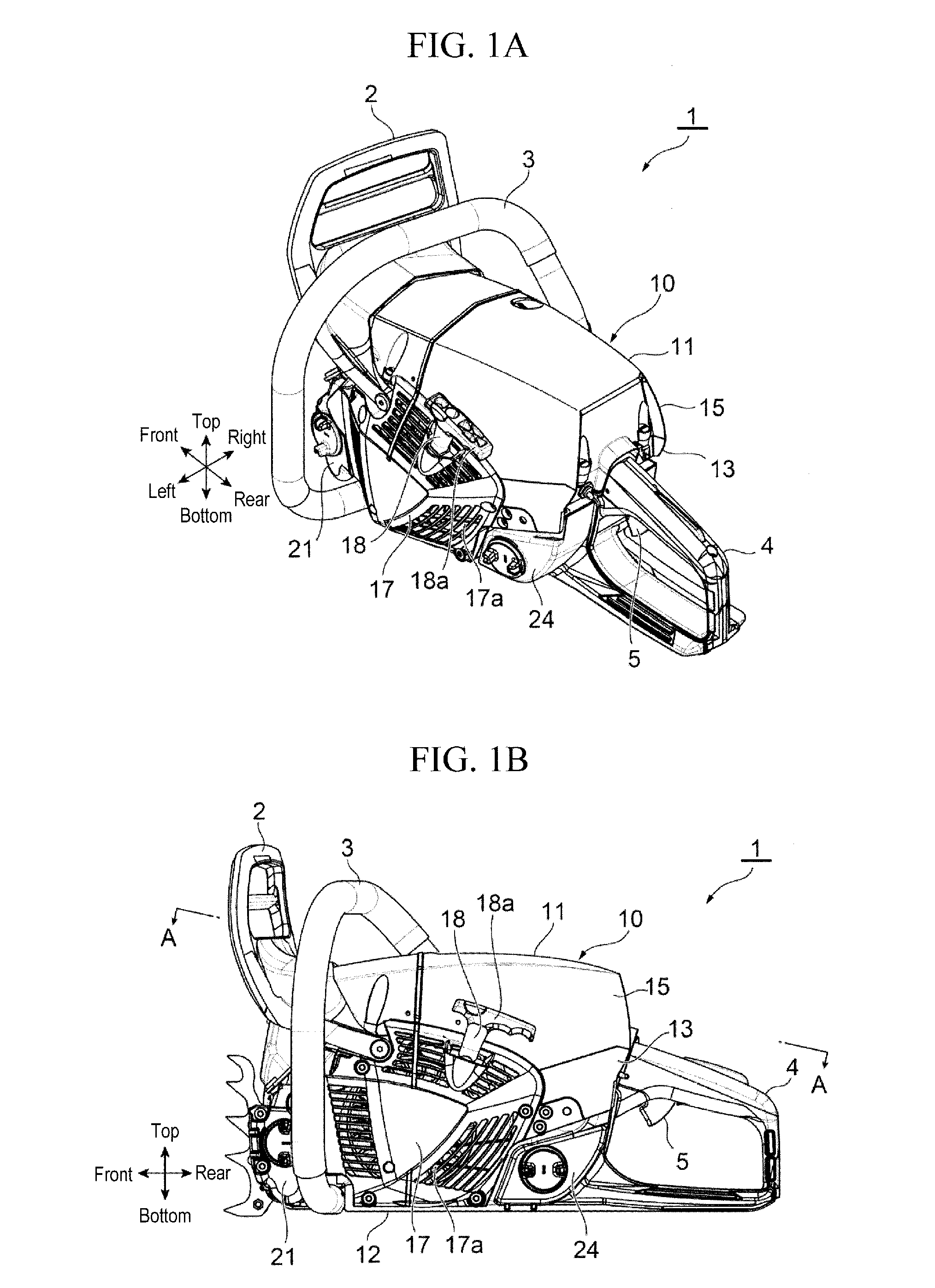
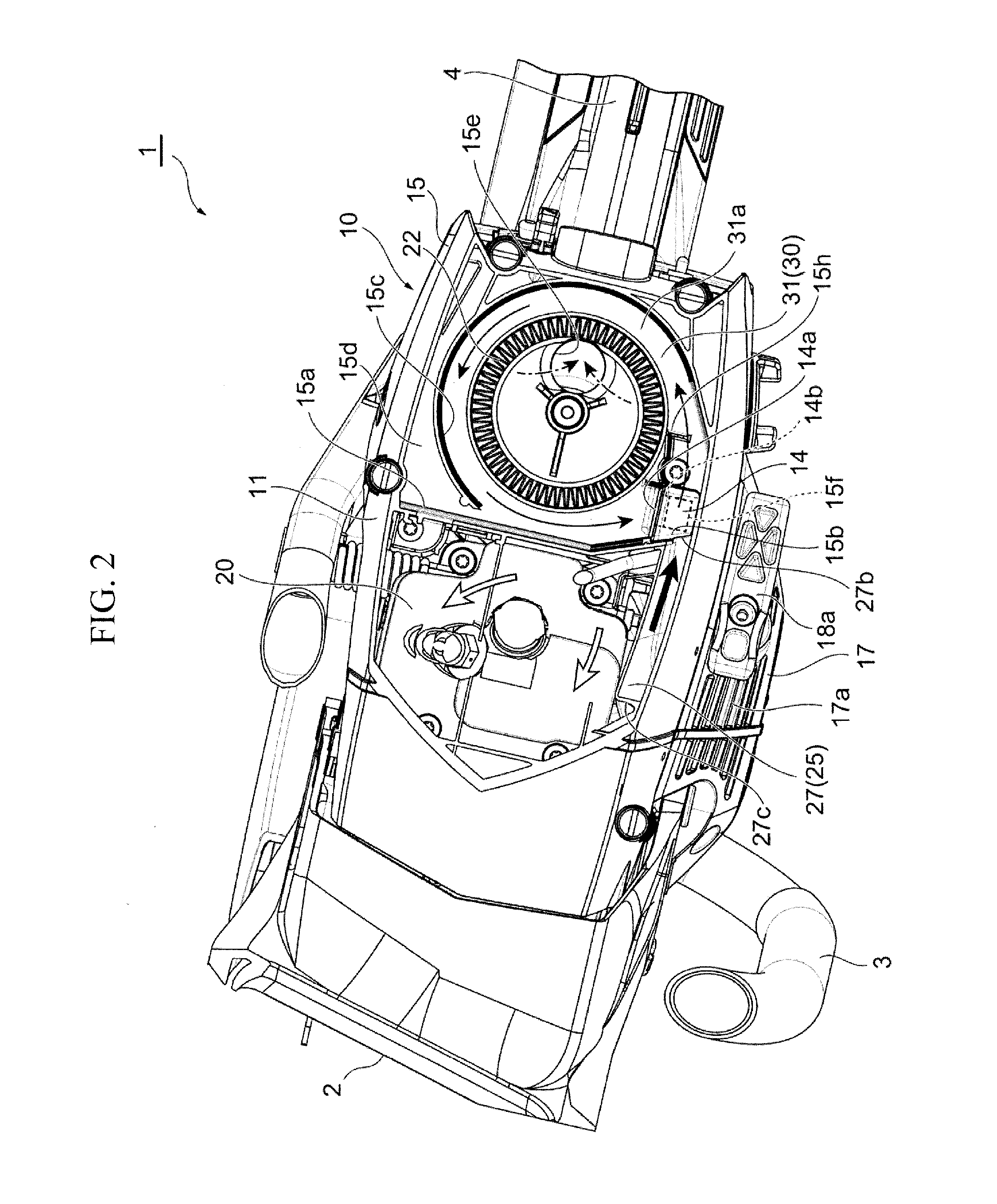
[0044]Hereafter, embodiments of a power working machine according to the present invention will be described referring to the drawings. In the present specification, for ease of description, description that represents a direction, such as above and below, left and right, and front and rear, is based on a direction arrow indication shown in each drawing as a reference and is not intended to indicate a direction and a position in the actual use state.

[0045]FIGS. 1A and 1B are an overall perspective view and a left side view, respectively, in which an embodiment of a chain saw as a power working machine according to the present invention is seen obliquely from the rear, and FIG. 2 is a cross-sectional view taken along line A-A of FIG. 1B. Moreover, FIGS. 3 and 5 are an overall perspective view and an essential-part enlarged plan view, respectively, showing a state in which a recoil starter case and a cylinder cover of the chain saw shown in FIGS. 1A and 1B are detached, seen obliquely...


PUM


Abstract

Provided is a portable power working machine that is designed to suppress mixing of dust into air sucked into an air intake system of an air-cooled internal combustion engine mounted as a driving power source for working units, for example, and reliably prevent an air cleaner provided to the air intake system of the internal combustion engine from being clogged with dust, and thus eliminate the necessity of frequently cleaning the air cleaner. An air intake port of an air intake passage is arranged on the opposite side of the internal combustion engine with respect to a straightening passage formed around a cooling fan, so that, of the air released from a discharge port of the straightening passage, at least part of air released toward the opposite side of the internal combustion engine with respect to the straightening passage is taken into the air intake passage via the air intake port.

Description

CLAIM OF PRIORITY[0001]The present application claims priority from Japanese patent application JP 2015-049437 filed on Mar. 12, 2015, the content of which is hereby incorporated by reference into this application.BACKGROUND[0002]1. Technical Field[0003]The present invention relates to a power working machine, and in particular, to a portable power working machine, such as a chain saw, an engine cutter, and a hedge trimmer, that is designed to prevent as much as possible an air cleaner attached to an air intake system of an internal combustion engine mounted on the power working machine as a driving power source for driving working components from being clogged with dust.[0004]2. Background Art[0005]A portable power working machine, such as a chain saw, is typically constructed such that a small air-cooled internal combustion engine acting as a driving power source for driving working components, such as a saw chain, is mounted in a main body housing, that a cooling fan driven by th...

Claims


Application Information

Patent Timeline
IPC IPC(8): F02M35/06F02M35/10F02M35/024
CPCF02M35/06F02M35/1017F02M35/024F02M35/0226F02B63/02Y02T10/12
Inventor KAWAMURA, KUNIMUNEUMETANI, KAZUHIRONAKAGANNA, HIROSHIKOBAYASHI, BUHEI
Owner YAMABIKO CORP
Learn More