Out-of-band data center management via power bus
a data center and power bus technology, applied in the field of out-of-band data center management via power bus, can solve the problems of multiple concurrent transmitting devices, limiting the use of specification-compliant buses, and requiring expensive serial concentrators in the rack
- Summary
- Abstract
- Description
- Claims
- Application Information
AI Technical Summary
Benefits of technology
Problems solved by technology
Method used
Image

Examples
embodiment 1
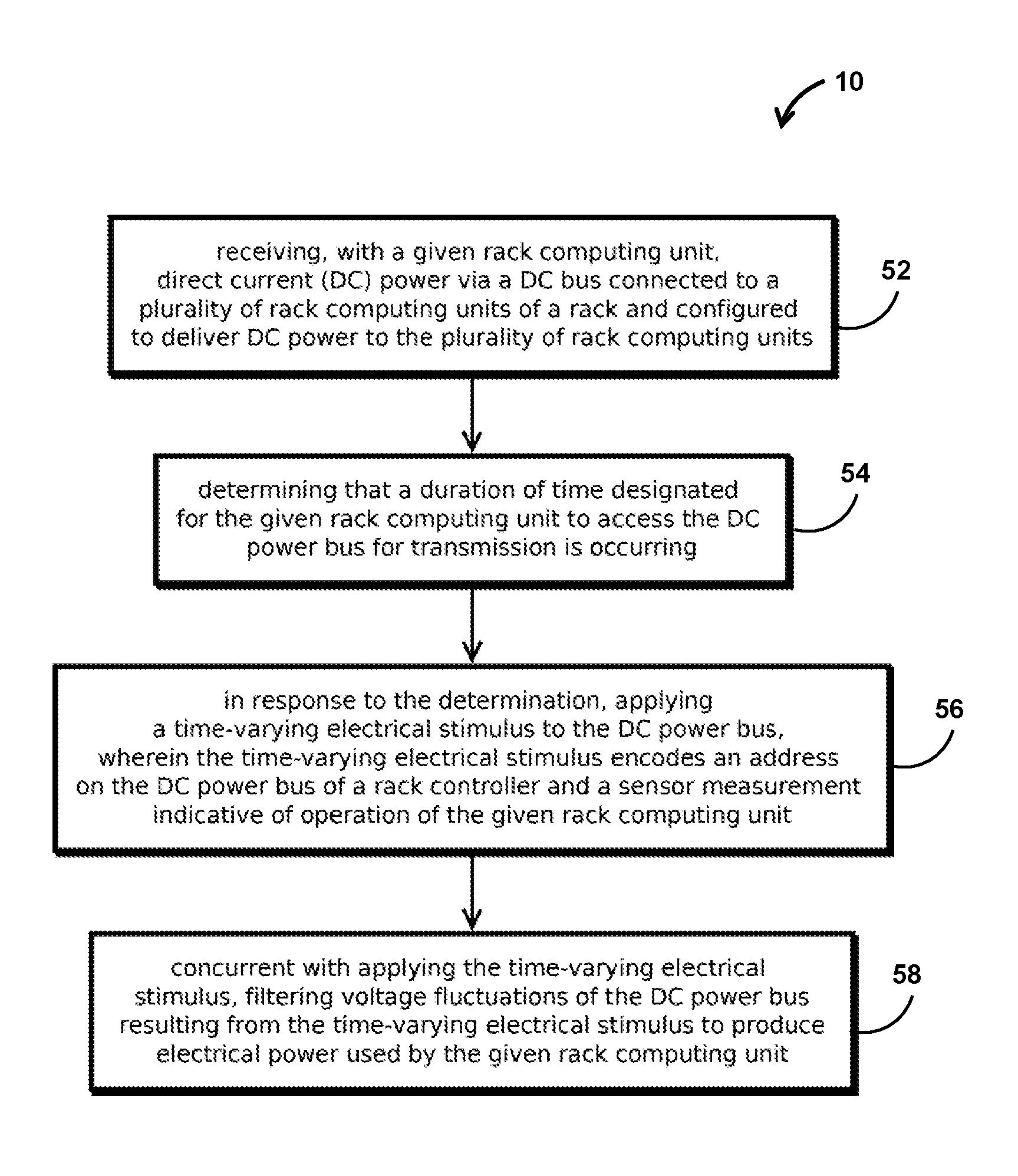
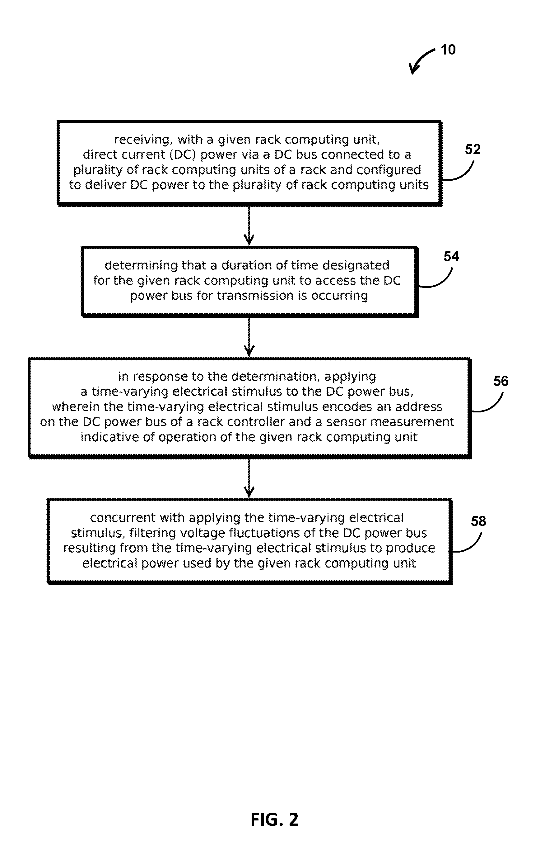
2. The method of embodiment 1, wherein the time-varying electrical stimulus comprises varying a resistance to a lower voltage or a higher voltage than a voltage of the DC bus.
3. The method of any of embodiments 1-2, wherein the time-varying electrical stimulus comprises varying an impedance of the bus.
4. The method of any of embodiments 1-3, wherein the time-varying electrical stimulus comprises varying a current drawn from the bus or driven onto the bus.
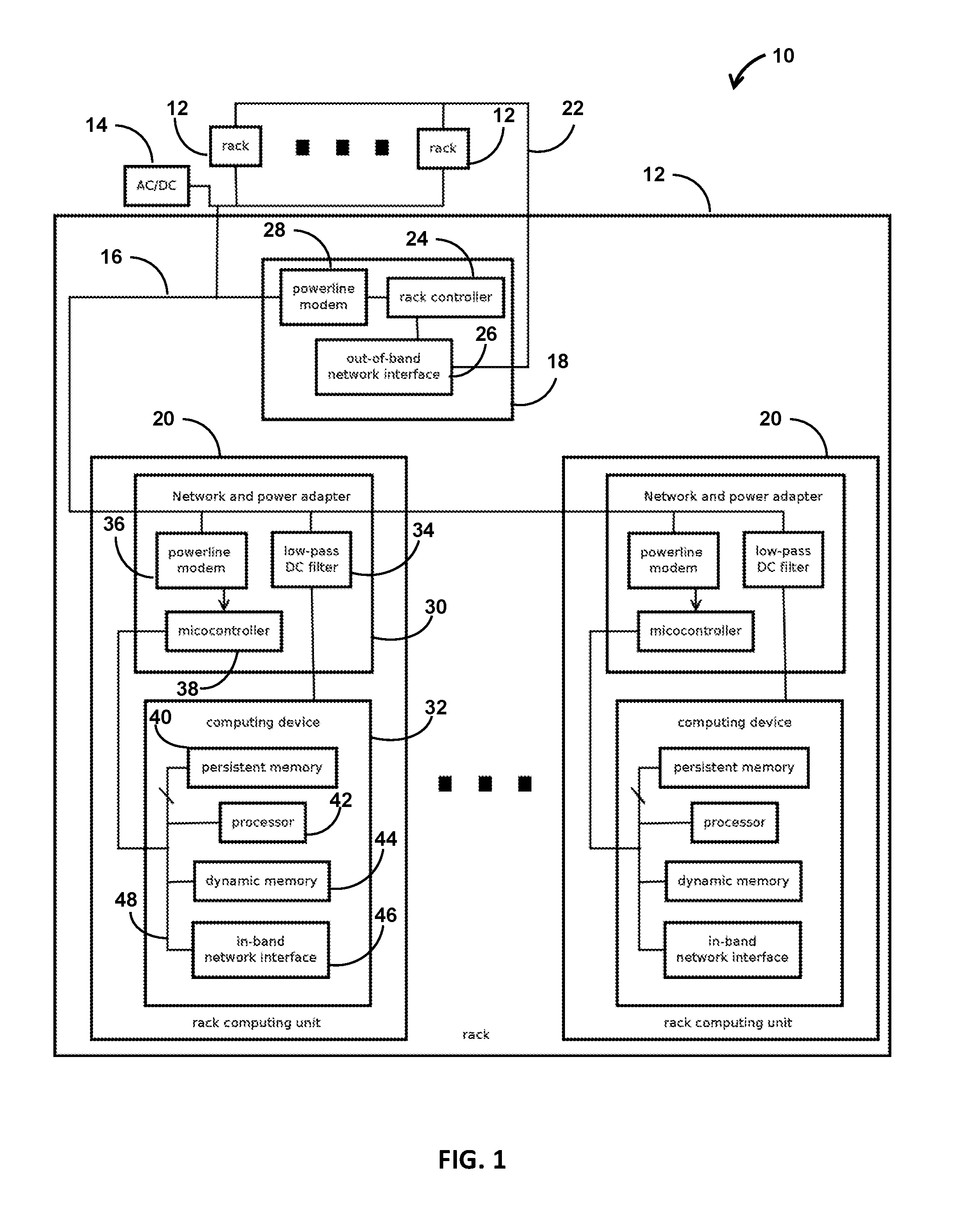
5. The method of any of embodiments 1-4, wherein the DC power bus includes a generally straight conductive member extending along a side of the rack and having an exposed electrically conductive surface that delivers power to a contact on each rack computing unit.
6. The method of any of embodiments 1-5, comprising: determining that another rack computing unit on the DC power bus is transmitting concurrent with applying the time-varying electrical stimulus and, in response, selecting a different duration of time based on a random val...
embodiment 11
12. The system of embodiment 11, wherein the network and power adapter comprises: a low-pass filter operative to shield, at least in part, a respective rack computing unit from fluctuations in DC power on the DC power bus.
13. The system of any of embodiments 11-12, wherein the network and power adapter has memory storing instructions that when executed are operative to detect that two network and power adapters are transmitting concurrently and change a transmit time for the respective network and power adapter on the bus.
14. The system of any of embodiments 11-13, wherein a given network and power adapter is configured to maintain control of the DC power bus after receiving a message from the controller until the given network and power adapter transmits a response.
15. The system of any of embodiments 11-14, wherein the network and power adapters are configured to arbitrate access to the DC power bus with time division multiplexing.
16. The system of any of embodiments 11-15, wherei...
embodiment 17
18. The method of embodiment 17, wherein an address space of the DC power bus is distinct from the out-of-band Ethernet network.
19. The method of any of embodiments 11-18, comprising a respective inductor disposed in series between the powerline bus and each respective rack computing unit.
20. The method of any of embodiments 11-19, comprising: a rack computing unit disposed in each of the receptacles, each rack computing unit having memory storing instructions of an operating system and an application configured to exchange data over an in-band network connected to the respective rack computing unit.
PUM
 Abstract
Description
Claims
Application Information
 - R&D
- Intellectual Property
- Life Sciences
- Materials
- Tech Scout
- Unparalleled Data Quality
- Higher Quality Content
- 60% Fewer Hallucinations
Browse by: Latest US Patents, China's latest patents, Technical Efficacy Thesaurus, Application Domain, Technology Topic, Popular Technical Reports.
© 2025 PatSnap. All rights reserved.Legal|Privacy policy|Modern Slavery Act Transparency Statement|Sitemap|About US| Contact US: help@patsnap.com