

Power receiving device and power transmitting device
a power receiving device and a technology for transmitting devices, applied in the direction of transformer/inductance magnetic cores, cores/yokes, transportation and packaging, etc., to achieve the effect of minimizing an induced current and minimizing a magnetic flux
- Summary
- Abstract
- Description
- Claims
- Application Information
AI Technical Summary
Benefits of technology
Problems solved by technology
Method used
Image

Examples
Embodiment Construction
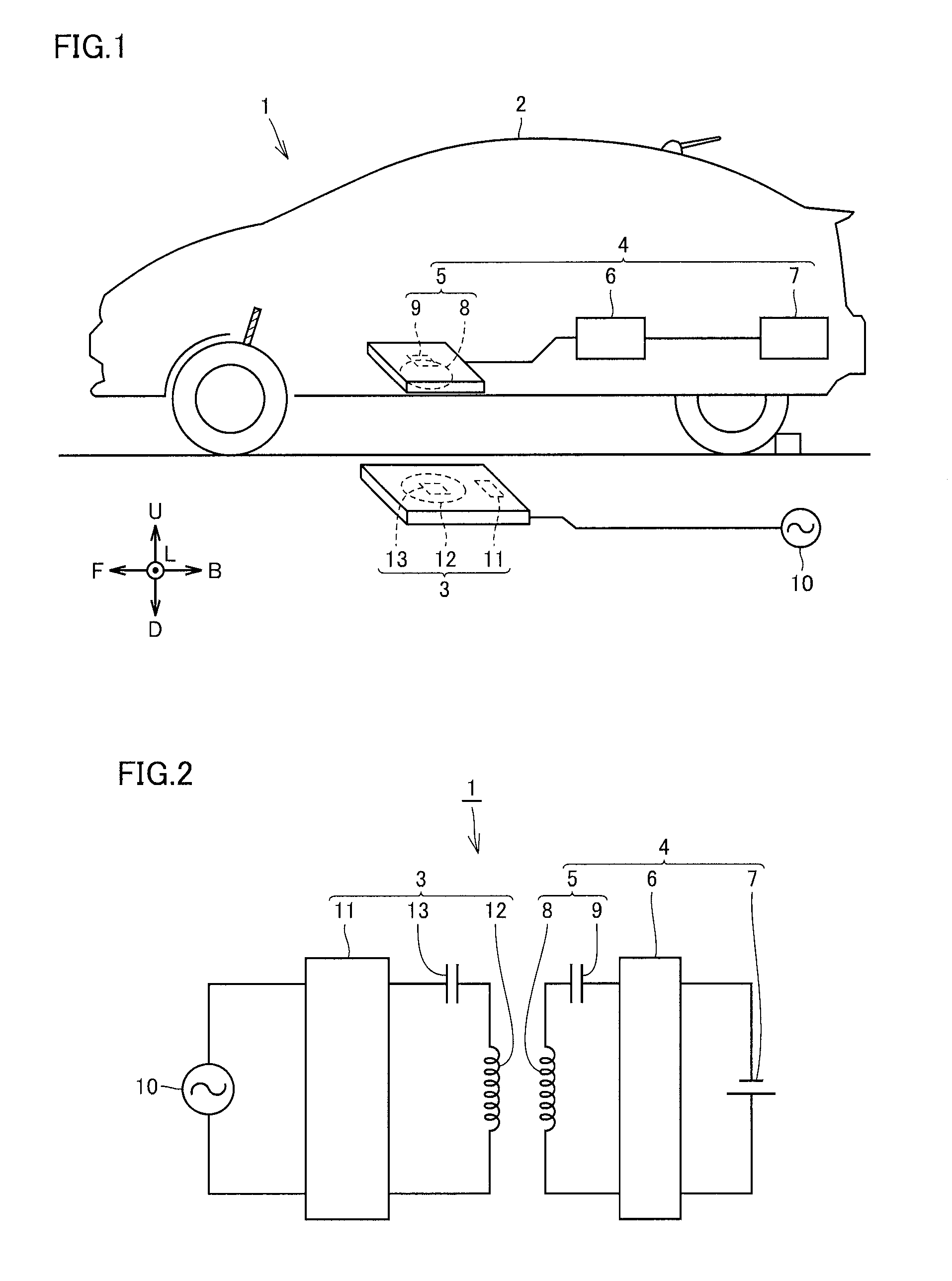
[0033]FIG. 1 is a schematic diagram schematically showing a contactless charging system 1, and FIG. 2 is a circuit diagram schematically showing the contactless charging system 1. As shown in FIG. 1 and FIG. 2, contactless charging system 1 includes a power receiving unit 4 mounted on a vehicle 2, and a power transmitting device 3 transmitting electric power to power receiving unit 4 contactlessly.
[0034]Power receiving unit 4 includes a power receiving device 5 receiving electric power transmitted from power transmitting device 3, a rectifier 6 converting alternating current (AC) power received by power receiving device 5 into direct current (DC) power and also adjusting it in voltage, and a battery 7 storing DC power supplied from rectifier 6.
[0035]The electric power stored in battery 7 is supplied to a driving motor (not shown) and the like, and the driving motor drives a vehicular wheel.
[0036]Power receiving device 5 includes a power receiving coil 8 and a power receiving capacit...
PUM
 Abstract
Description
Claims
Application Information