
LED driving apparatus and driving method for continuously driving LED

Inactive Publication Date: 2016-09-15
SEOUL SEMICONDUCTOR
View PDF7 Cites 2 Cited by
  • Summary
  • Abstract
  • Description
  • Claims
  • Application Information

AI Technical Summary

Benefits of technology

The present invention provides an LED driving apparatus and method that can reduce flickering, decrease energy storage capacity, reduce manufacturing cost, and miniaturize an LED lighting fixture by not connecting an energy chargeable and dischargeable element for providing a second driving voltage. The invention also improves uniformity of an emitting time between LED groups and reduces partial deterioration of LED groups by selectively driving LED groups in a non-emitting interval. The energy chargeable and dischargeable element maintains a relatively low energy storage capacity in the non-emitting interval by not connecting it for providing the second driving voltage to the total of LED groups but connecting it to an intermediate node of the LED groups connected in series to each other, reducing the required relatively low energy storage capacity. The invention also allows the energy chargeable and dischargeable element to charge more charges in a relatively long interval of a low voltage value.

Problems solved by technology

In a case of the direct current driving mode, there are problems that an alternating current-to-direct current (AC-DC) converter such as a switching mode power supply (SMPS), or the like is necessarily required, the power converter increases cost of manufacturing a lighting fixture, makes miniaturization of the lighting fixture difficult, degrades energy efficiency of the lighting fixture, and shortens a lifespan of the lighting fixture due to a short lifespan of the power converter.
However, a circuit according to the above-mentioned technology has a problem that a flicker phenomenon in which a user recognizes a flicker of a lighting due to a long non-emitting interval of the LED occurs as well as a problem that a power factor is degraded due to a non-match between an input voltage and a current output from the LED.
However, there are problems that the flicker phenomenon still occurs in the non-emitting interval in which the input voltage does not reach Vf1 and light characteristics of the lighting fixture are not uniform because emitting times for each light emitting module of the LED are different from each other.
However, according to the above-mentioned technologies, there is a problem that total harmonic distortion (THD) is rather deteriorated due to element characteristics in which the current is sharply increased at a timing in which the smooth capacitor begins to charge.
In addition, there is a problem that high capacitance is required because the smooth capacitor should maintain a voltage of at least Vf3 or more in order to drive all LEDs in the non-emitting interval.
In addition, due to the above-mentioned problems, there is a problem that cost of the smooth capacitor is increased and it is difficult to miniaturize the LED lighting fixture.

Method used


Image

  • LED driving apparatus and driving method for continuously driving LED
  • LED driving apparatus and driving method for continuously driving LED
  • LED driving apparatus and driving method for continuously driving LED

Examples


Embodiment Construction

[0057]Exemplary embodiments of the present invention will be described below in detail with reference to the accompanying drawings showing specific exemplary embodiments in which the present invention may be practiced. These exemplary embodiments will be described in detail for those skilled in the art in order to practice the present invention. It should be appreciated that various exemplary embodiments of the present invention are different but do not have to be exclusive. For example, specific shapes, configurations, and characteristics described in an exemplary embodiment of the present invention may be implemented in another exemplary embodiment without departing from the spirit and the scope of the present invention. In addition, it should be understood that positions or arrangements of individual components in each disclosed exemplary embodiment may be changed without departing from the spirit and the scope of the present invention. Therefore, a detailed description described...


PUM


Abstract

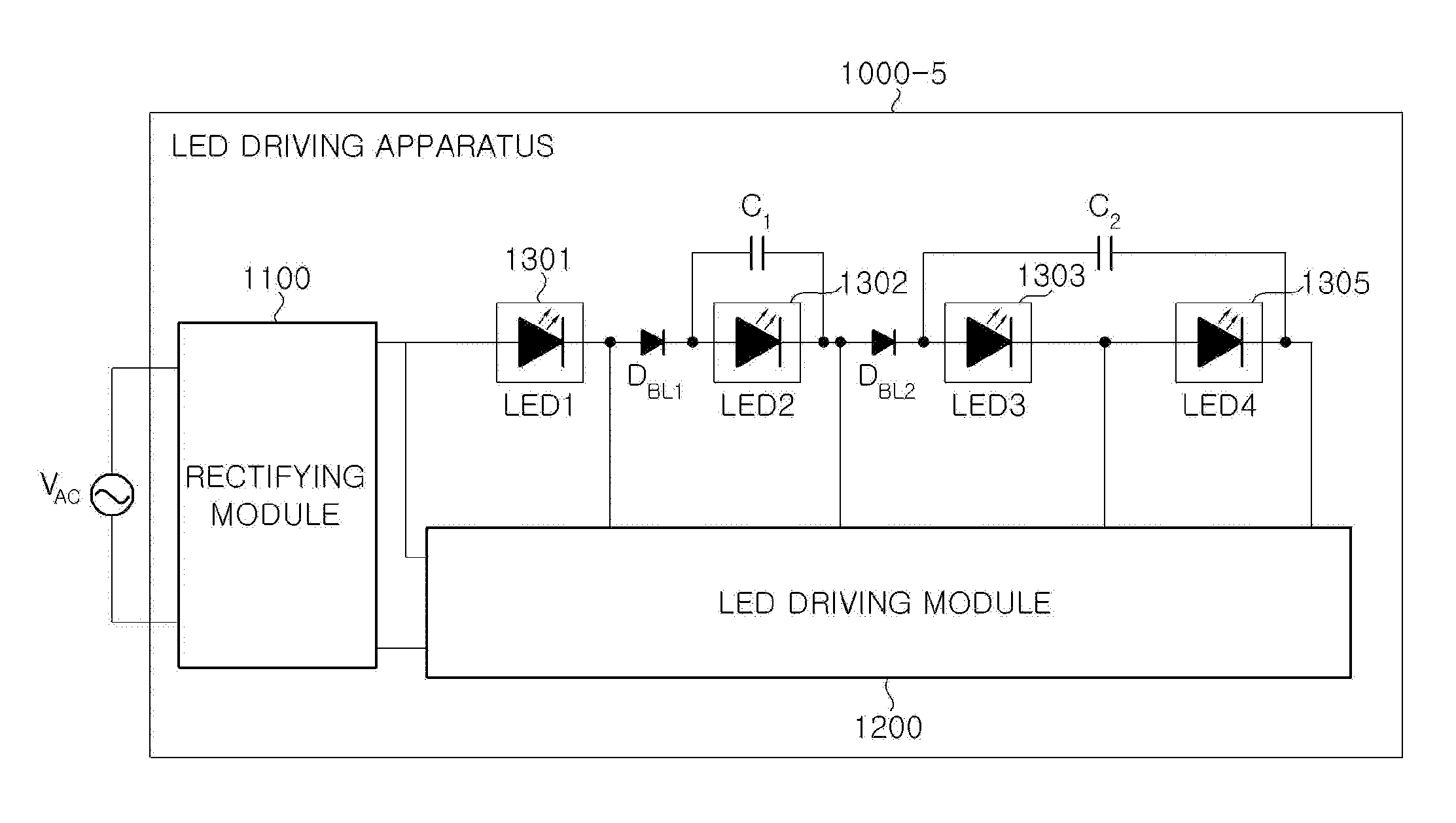
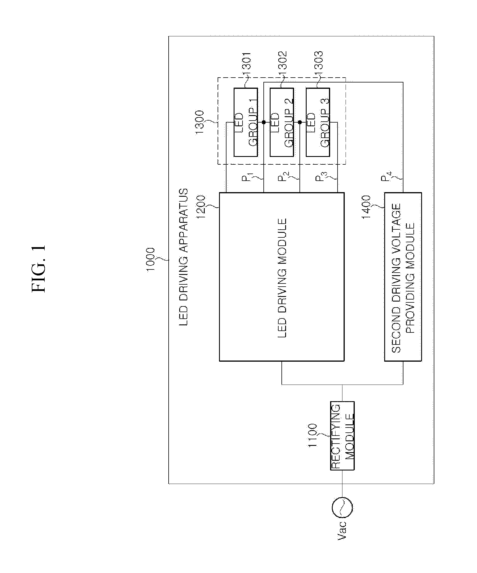
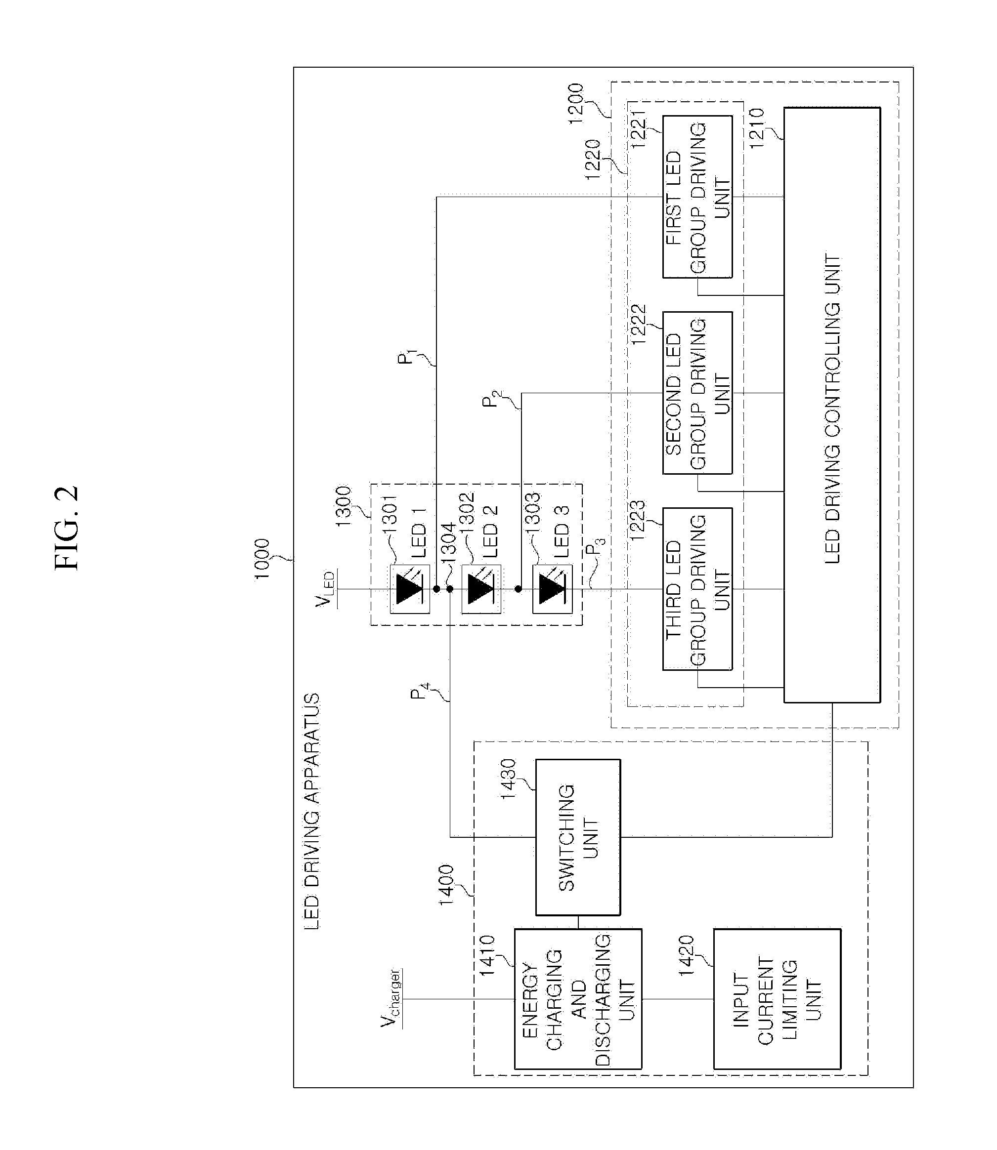
A light-emitting diode (LED) driving apparatus includes a rectifying module configured to rectify an alternating current voltage and output a first driving voltage, an LED light emitting module including a first LED group, and a second LED group to an n-th LED group, and configured to receive the first driving voltage from the rectifying module, n being a positive integer of two or more, an LED driving module configured to sequentially drive the first LED group to the n-th LED group according to a voltage level of the first driving voltage, and a second driving voltage providing module connected in parallel to at least one LED group of the second LED group to the n-th LED group.

Description

CROSS-REFERENCE TO RELATED APPLICATIONS[0001]This application is a Continuation-in-Part of U.S. patent application Ser. No. 14 / 434,031, filed on Apr. 7, 2015, which is the National Stage Entry of International Application No. PCT / KR2013 / 008951, filed on Oct. 7, 2013, and claims priority from and the benefit of Korean Patent Application No. 10-2012-0111211, filed on Oct. 8, 2012, which are all incorporated herein by reference for all purposes as if fully set forth herein.BACKGROUND[0002]1. Field[0003]Exemplary embodiments of the present invention relate to a light emitting diode (LED) driving apparatus and driving method for continuously driving an LED, and more particularly, to an LED driving apparatus and driving method for continuously driving an LED capable of compensating for a light output of an LED lighting using an energy chargeable and dischargeable element and / or circuit.[0004]2. Discussion of the Background[0005]A light emitting diode (LED) is generally driven in a direct ...

Claims


Application Information

Patent Timeline
IPC IPC(8): H05B33/08H05B44/00
CPCH05B33/0812H05B33/0842H05B33/0884H05B45/395H05B45/44Y02B20/30H05B45/54H05B45/355
Inventor JUNG, HYE MANKANG, HYUN GUHAN, SANG WOOK
Owner SEOUL SEMICONDUCTOR
Learn More