Folding propeller

Active Publication Date: 2016-09-22
FLEXOFOLD APS
View PDF3 Cites 4 Cited by
  • Summary
  • Abstract
  • Description
  • Claims
  • Application Information

AI Technical Summary

Benefits of technology

[0007]It is an object of the invention to provide a folding propeller that is rather corrosion resistant, has a low moment of inertia, and where slack between the individual parts of the folding propeller can be adjusted according to production tolerances and to wear. It

Problems solved by technology

Another rather important issue when it comes to propellers for boats is corrosion and effectiveness.
Another important subject is the effectiveness of the propeller, which can be compromised rather drastically due to fouling on the propeller parts.
Until now the design of folding pro

Method used


Image

  • Folding propeller
  • Folding propeller
  • Folding propeller

Examples


Example

[0043]In the following text, the figures will be described one by one and the different parts and positions seen in the figures will be numbered with the same numbers in the different figures. Not all parts and positions indicated in a specific figure will necessarily be discussed together with that figure.

DETAILED DESCRIPTION OF THE INVENTION

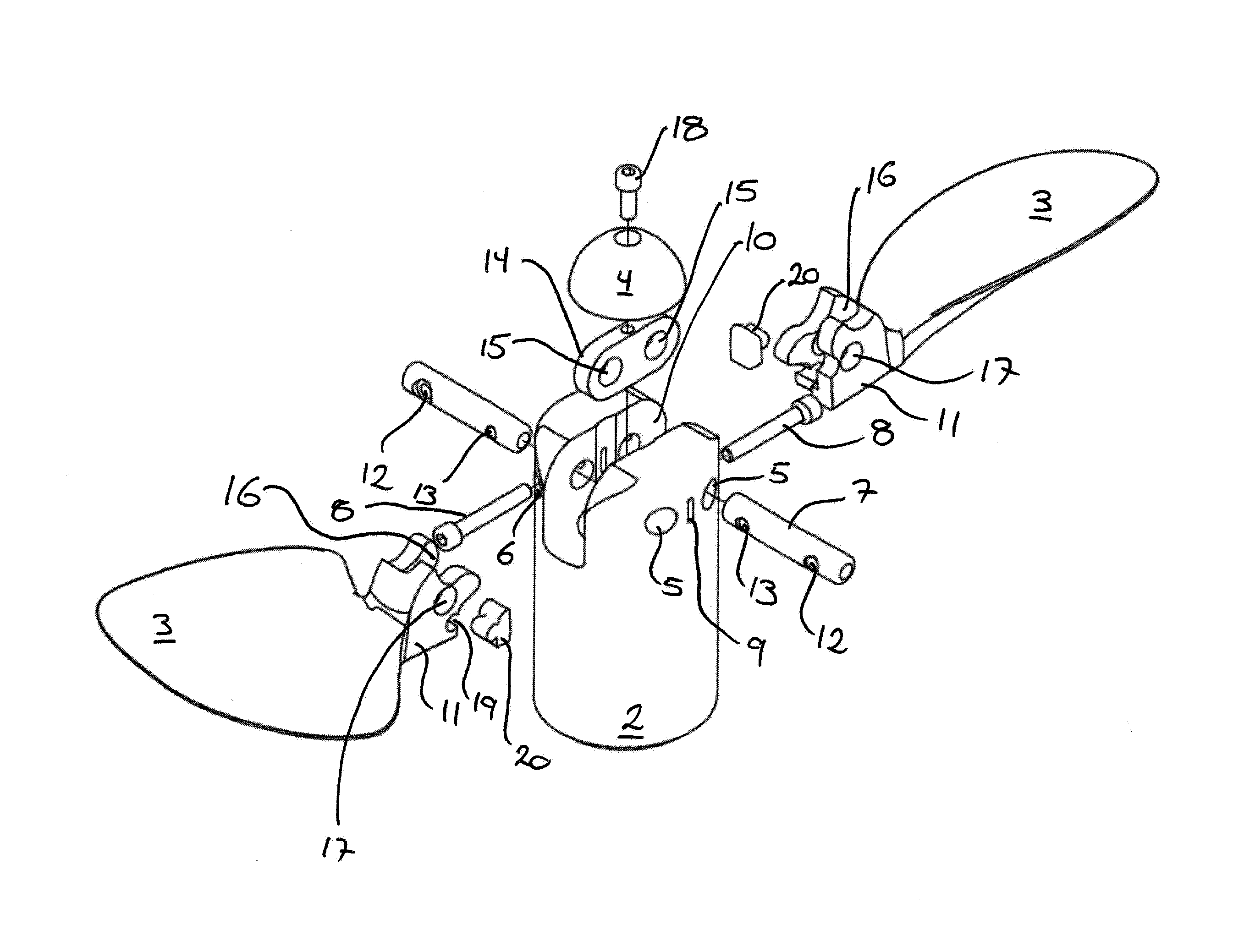
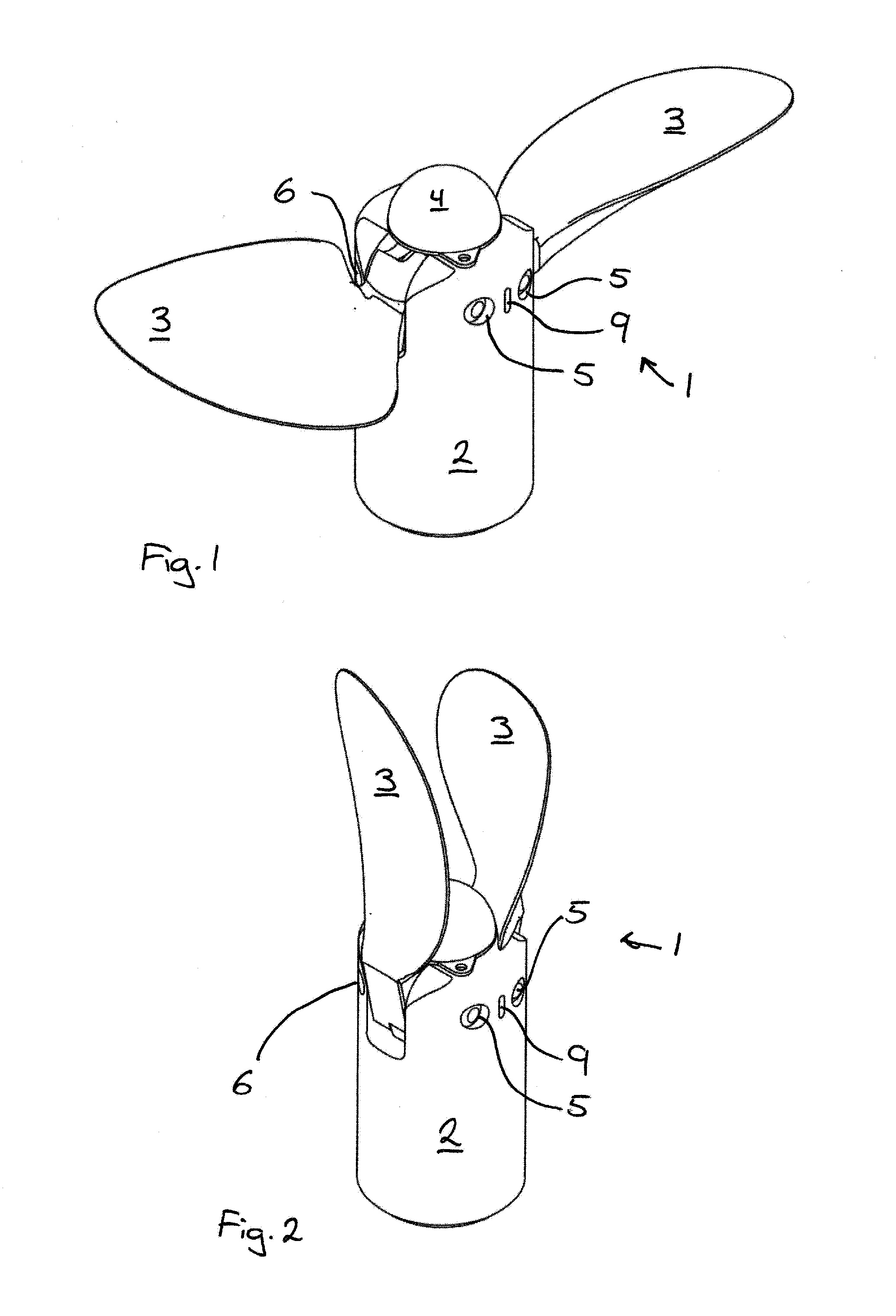
[0044]In FIG. 1 a two bladed folding propeller 1 is seen in an operative position, where the blades 3 are unfolded and extending in a more or less radial direction from the hub 2. At the end of the hub 2 an anode 4 is seen and on the side of the hub 2 the first set of holes 5 in the hub 2 is seen. In said first set of holes 5 the pivot pins 7 are arranged and secured.

[0045]FIG. 2 show the same folding propeller 1 as seen in FIG. 1, but here, in an inoperative position, with the blades 3 folded and pointing in an axial direction.

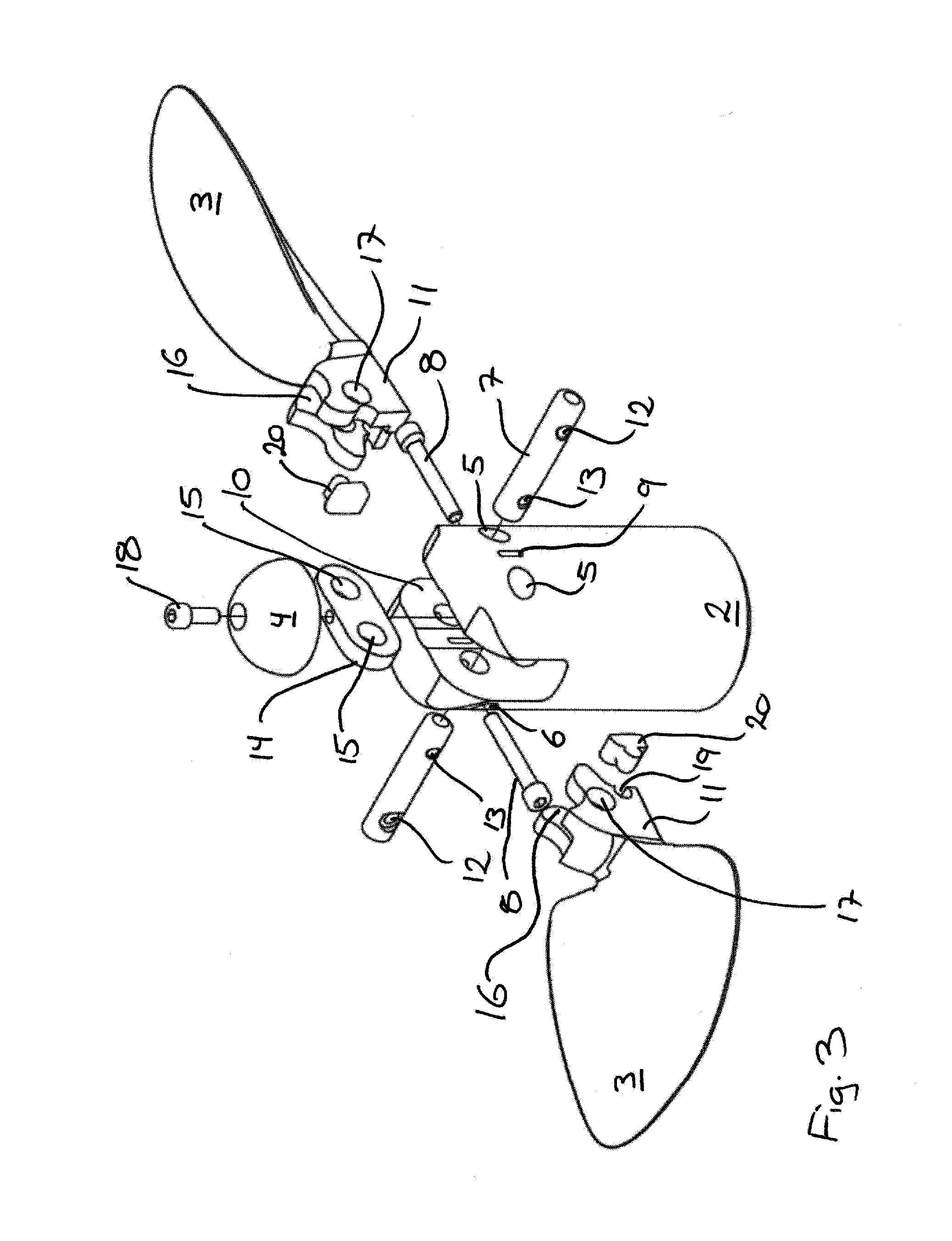
[0046]In FIG. 3 the same two bladed folding propellers 1, as also seen in the preceding figures, are seen, but here in...


PUM


Abstract

A folding propeller for a boat, e.g., for a sailboat or a multihull yacht, and a method for installing and/or adjusting such a folding propeller, where said folding propeller has a hub for directly or indirectly fastening at a driveshaft connected to a motor, where said folding propeller further has at least two individual blades, where each of said blades has a root arranged to pivot around a pivot pin at said hub to be either in a first, operative position, where the blades are pointing mainly in a radial direction, and in a second, inoperative position, where the blades are pointing mainly in an axial direction, where said hub has one or more cut outs for said blades roots and further has a first set of holes for installing said pivot pins and a second set of holes for installing a locking device for engagement with said pivot pins.

Description

BACKGROUND OF THE INVENTION[0001]1. Field of the Invention[0002]The present invention relates to a folding propeller for a boat, e.g., for a sailboat or a multihull yacht, where said folding propeller comprises a hub for directly or indirectly fastening at a driveshaft connected to a motor, where said folding propeller further comprises at least two individual blades, where each of said blades comprises a root arranged to pivot around a pivot pin at said hub in order to either be in a first and operative position, where the blades are pointing mainly in a radial direction, or in a second and inoperative position, where the blades are pointing mainly in an axial direction, where said hub comprises one or more cut outs for said blade roots and further comprises a first set of holes for installing said pivot pins and a second set of holes for installing said locking means for engagement with said pivot pins. The invention further comprises a method for installing and / or adjusting such ...

Claims


Application Information

Patent Timeline
IPC IPC(8): B63H1/22
CPCB63H1/22
Inventor SKRYDSTRUP, JACK
Owner FLEXOFOLD APS
Why Eureka
Try Eureka