Tiltrotor Unmanned Aerial Vehicle

a technology of unmanned aerial vehicles and tilting wheels, which is applied in the direction of instruments, vertical landing/taking-off aircraft, transportation and packaging, etc., can solve the problem of more limited flight field of drones like these, and achieve the effect of improving maneuverability

Active Publication Date: 2016-09-22
AERO MACHINING LLC
View PDF26 Cites 87 Cited by
  • Summary
  • Abstract
  • Description
  • Claims
  • Application Information

AI Technical Summary

Benefits of technology

[0008]The invention is directed toward a UAV having a plurality of rotors position on axles extending longitudinally from a fuselage. The axles articulate the rotors from a vertical position, where the rotors provide lift, to ...

Problems solved by technology

The field of flight for drones like these is more limited ...

Method used


Image

  • Tiltrotor Unmanned Aerial Vehicle
  • Tiltrotor Unmanned Aerial Vehicle
  • Tiltrotor Unmanned Aerial Vehicle

Examples


Embodiment Construction

[0024]The claimed subject matter is now described with reference to the drawings. In the following description, for purposes of explanation, numerous specific details are set forth in order to provide a thorough understanding of the claimed subject matter. It may be evident, however, that the claimed subject matter may be practiced with or without any combination of these specific details, without departing from the spirit and scope of this invention and the claims.

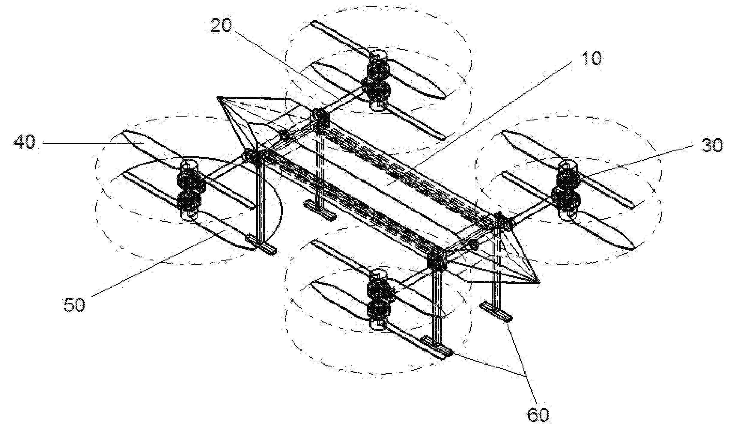
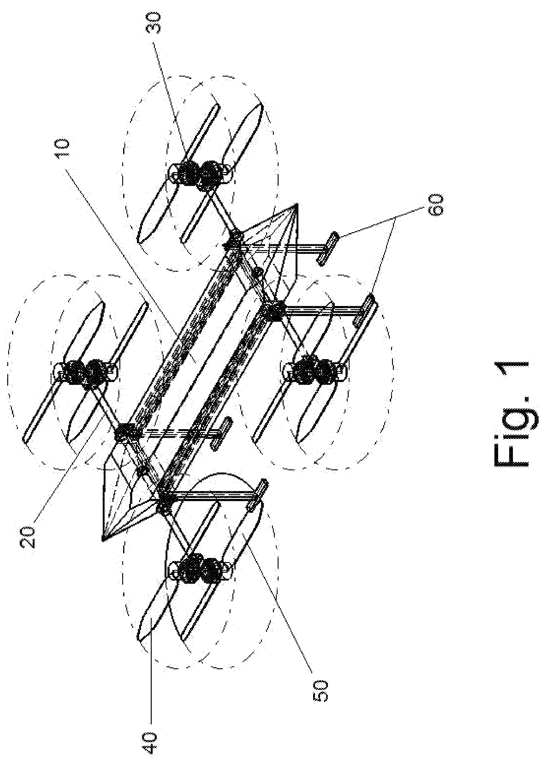
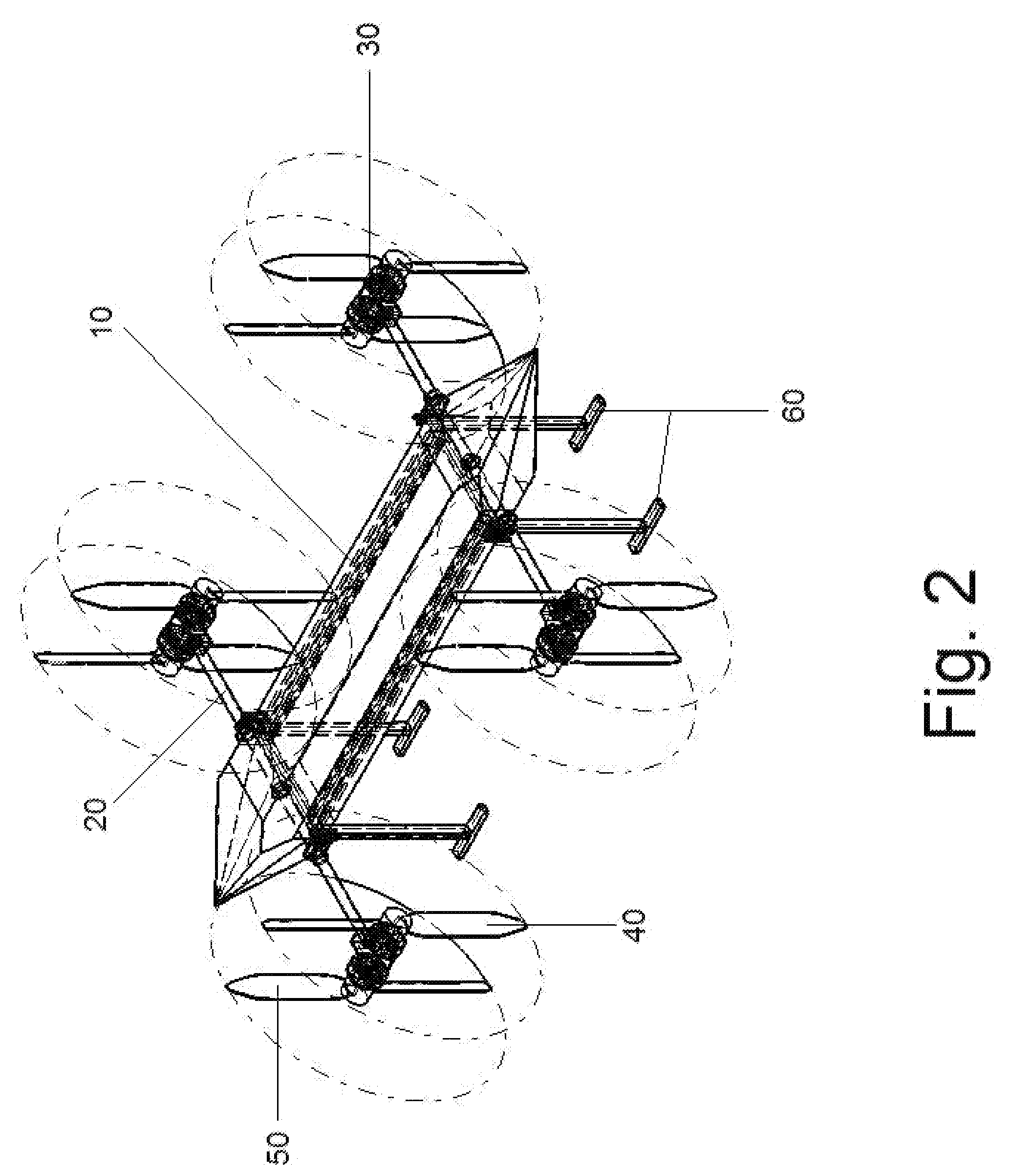
[0025]The invention is directed toward an unmanned aerial vehicle (UAV) having a plurality of pivotable rotors. The rotors are configured to operate in vertical mode—providing the UAV with lift—and horizontal mode—providing the UAV with thrust. In some embodiments the UAV may have a plurality of wings which generate the lift while the rotors are in horizontal mode. In the preferred embodiment, the rotors of the UAV are independently variable in speed, permitting the creation of asymmetric propulsion loads which can enhanc...


PUM


Abstract

The invention is directed toward a UAV having a plurality of rotors position on axles extending longitudinally from a fuselage. The axles articulate the rotors from a vertical position, where the rotors provide lift, to a horizontal position, where the rotors provide thrust. The UAV is configured such that the voltage provided to each rotor may be varied to adjust rotor speed, and thus thrust, independently, giving the UAV enhanced maneuverability.

Description

PRIORITY[0001]This application claims priority to U.S. provisional patent application No. 61 / 934,705, filed Feb. 1, 2014.FIELD OF INVENTION[0002]This invention pertains generally to unmanned aerial vehicles (UAVs) or unmanned aerial systems (UAS), and more particularly to a winged UAV's with pivotal rotors for vertical takeoffs and landings.BACKGROUND OF INVENTION[0003]Unmanned aerial vehicles (UAVs) are going in popularity for both military and consumer functions. Military drones are primarily winged flight vehicles that carry incendiary payloads to specific targets. These drones are remotely piloted to specific destinations where payloads are delivered. Because of the need for a quick response to complete military objectives, winged drones are primarily utilized. These drones tend to have a pair of wings which permit them to takeoff and land horizontally, in the manner performed by airplanes. Because the drones are winged, the lift necessary for flight is generated by airflow over...

Claims


Application Information

Patent Timeline
IPC IPC(8): B64C29/00B64C3/50G01S19/13B64C39/02
CPCB64C29/0033B64C39/024B64C3/50G01S19/13B64C2201/126B64C2201/042B64C2201/104B64C2201/108B64C2201/146B64C27/28B64U30/10B64U2101/00B64U50/19B64U30/20B64U2201/20
Inventor MALLARD, BRAD
Owner AERO MACHINING LLC
Why Eureka
Try Eureka