Deposition apparatus containing moving deposition source

a technology of deposition apparatus and deposition source, which is applied in the direction of chemical vapor deposition coating, vacuum evaporation coating, coating, etc., can solve the problems of difficult formation of uniform thin films and the generation of particles by the movement of the coating target, so as to effectively prevent the introduction of residual deposition materials and reduce the generation of particles

Inactive Publication Date: 2016-09-22
BMC +1
View PDF0 Cites 1 Cited by
  • Summary
  • Abstract
  • Description
  • Claims
  • Application Information

AI Technical Summary

Benefits of technology

[0009]According to the foregoing technical means of the present disclosure, it is possible to form a more uniform thin film and minimize generation of particles resulting from movement of a coating target, by fixing the coating target and moving the deposition source to control a distance between a surface of the coating target and the deposition source.
[0010]Also, it is possible to effectively prevent introduction of residual deposition materials into the supply unit resulting in generation of particles and introduction of particles into the coating target resulting in contamination of the surface of the coating target, by separating the supply unit from the deposition source through the particle shield in the inside of the vacuum chamber.

Problems solved by technology

Accordingly, there has been a problem in that it is difficult to form a uniform thin film.
Also, there has been a problem in that the movement of the coating target generates particles.

Method used


Image

  • Deposition apparatus containing moving deposition source
  • Deposition apparatus containing moving deposition source
  • Deposition apparatus containing moving deposition source

Examples


Embodiment Construction

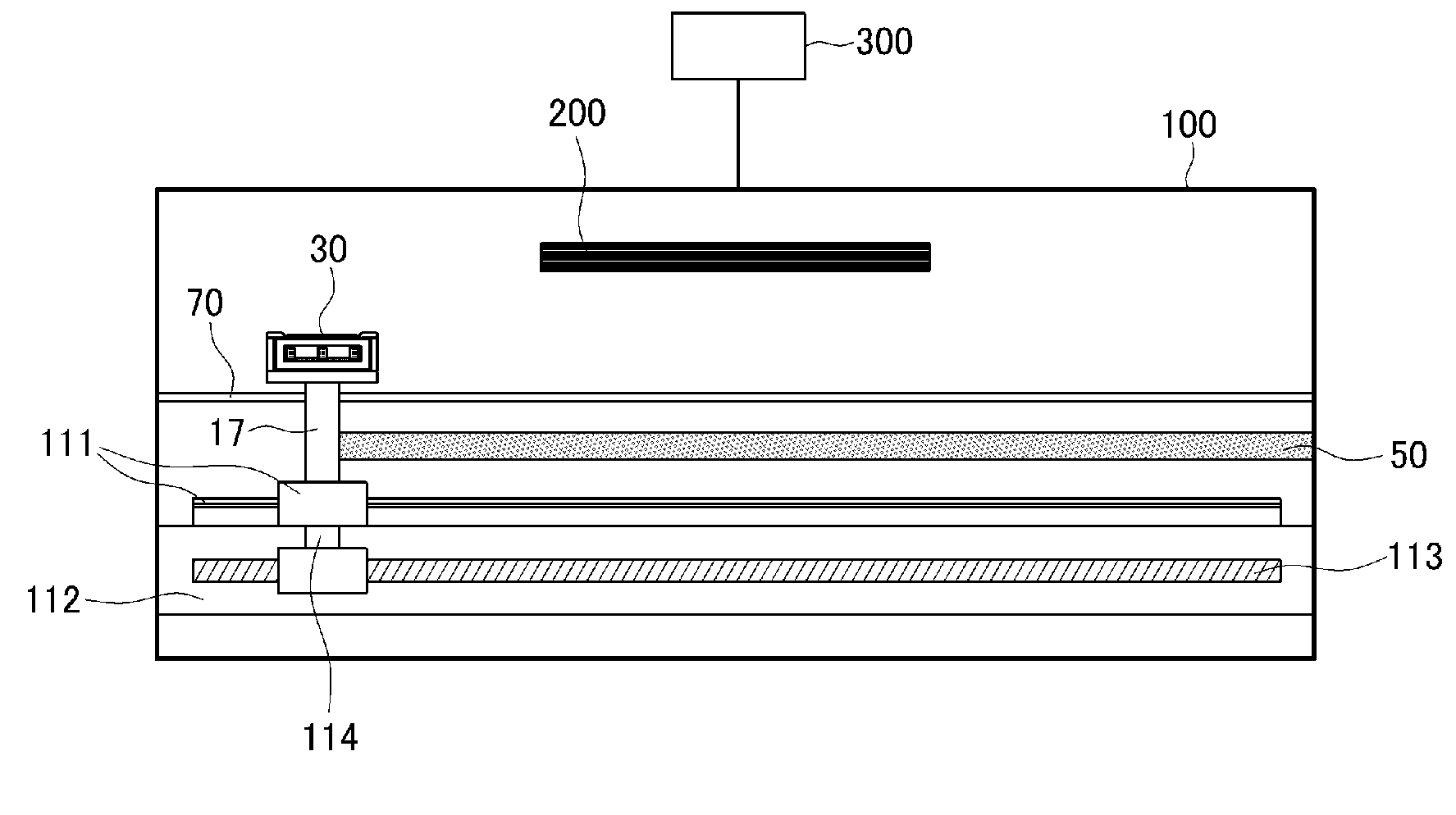
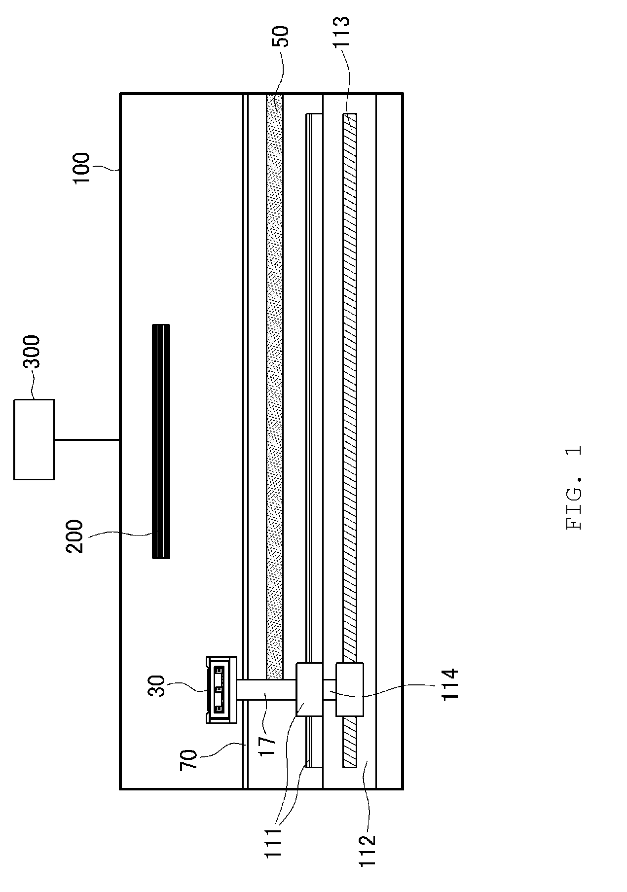
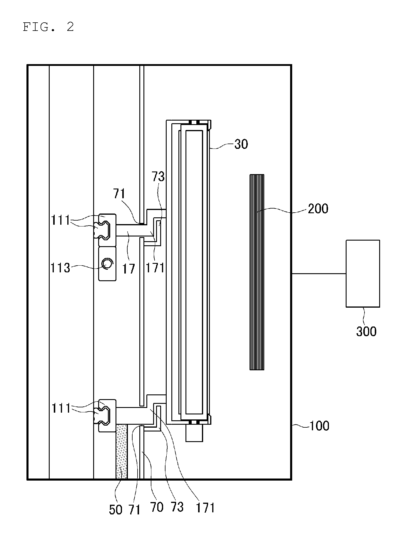
[0021]Hereinafter, illustrative embodiments of the present disclosure will be described in detail with reference to the accompanying drawings so that inventive concept may be readily implemented by those skilled in the art. However, it is to be noted that the present disclosure is not limited to the illustrative embodiments but can be realized in various other ways. In the drawings, certain parts not directly relevant to the description are omitted to enhance the clarity of the drawings, and like reference numerals denote like parts throughout the whole document.

[0022]Throughout the whole document, the term “on” that is used to designate a position of one element with respect to another element includes both a case that the one element is adjacent to the another element and a case that any other element exists between these two elements.

[0023]Throughout the whole document, the term “comprises or includes” and / or “comprising or including” used in the document means that one or more o...


PUM

PropertyMeasurementUnit
distanceaaaaaaaaaa
circumferenceaaaaaaaaaa
vacuumaaaaaaaaaa

Abstract

A deposition apparatus for depositing a thin film on a surface of a coating target within a vacuum chamber is disclosed. The deposition apparatus includes a deposition source that supplies a material for forming the thin film; a supply unit that supplies at least one of coolant, power supply, and a process gas to the deposition source; and a moving unit that moves the deposition source within the vacuum chamber.

Description

TECHNICAL FIELD[0001]The present disclosure relates to a deposition apparatus containing a moving deposition source.BACKGROUND ART[0002]When manufacturing liquid crystal displays and organic light emitting displays, a transparent electrode, a metal electrode, an insulating film, etc., are formed through a physical vapor deposition (PVD) method or a chemical vapor deposition (CVD) methods such as a plasma enhanced chemical vapor deposition (PECVD) method.[0003]A conventional physical or chemical vapor deposition apparatus uses a method of fixing a deposition source and moving or spinning a coating target. Since the deposition source should be connected to various devices for supplying coolant, power supply, a process gas, etc., it should be necessarily in the fixed form.[0004]However, in case of depositing a thin film on a coating target in a bent form through the deposition apparatus containing the fixed deposition source, a distance between a surface of the coating target and the d...

Claims


Application Information

Patent Timeline
Patent Type & Authority Applications(United States)
IPC IPC(8): C23C14/24
CPCC23C14/24C23C14/243C23C16/448
Inventor HONG, CHARLIELEE, MAN HO
Owner BMC
Why Eureka
Try Eureka