
Rare earth metal member and making method

a rare earth metal and metal member technology, applied in the direction of screws, washers, ways, etc., can solve the problems of affecting semiconductor performance and reliability, requiring increased machining costs, and affecting the performance of semiconductors, so as to achieve no drop in corrosion resistance and improve corrosion resistance or plasma resistance

Inactive Publication Date: 2010-03-09
SHIN ETSU CHEM IND CO LTD
View PDF10 Cites 2 Cited by
  • Summary
  • Abstract
  • Description
  • Claims
  • Application Information

AI Technical Summary

Benefits of technology

The present invention provides a rare earth metal member that is composed entirely of rare earth metal, has high purity, and is resistant to corrosion and plasma damage. The member has excellent electric conductivity and can be used in semiconductor manufacturing equipment and flat panel display manufacturing equipment. The invention also provides a method for preparing the rare earth metal member by machining an ingot containing not more than 100 ppm of metal elements other than rare earth metal and cleaning it with an organic acid-base capping agent solution. The rare earth metal member is free of surface contamination, has minimal particle generation, and has high purity.

Problems solved by technology

Regrettably, the ceramic members require an increased machining cost and suffer from the problem of particles left on the surface.
When the ceramic members are exposed to plasma in a corrosive gas atmosphere, corrosion gradually takes place, though to a varying extent, whereupon crystal grains spall off from the surface region, causing so-called particle contamination.
Once spalling off, particles are likely to deposit on or near the semiconductor wafer, lower electrode or the like to exert negative impact on etching precision or the like, detracting from the semiconductor performance and reliability.
At the site where such characteristics are required, anodized aluminum parts are often used, but suffer from problems like a short life and release of AlF particles.
However, the advanced plasma environment has a propensity for increasing energy, raising a problem that spark partially generates due to a tipping of the plasma balance.
Efforts have been made to reduce the size of surface irregularities and pores, but these countermeasures are unsatisfactory.
Thus this member cannot maintain the desired corrosion resistance on repeated use.
As compared with conventional etching conditions, the low-pressure high-density plasma has great influence on the plasma-resistant member, making more serious the problems including erosion by plasma, contamination of member components caused by the erosion, and contamination with the reaction products of surface impurities.
While metal machining tools are used for cutting, grinding and otherwise machining of members, the machined members are contaminated on their surface.
When used in a halogenic plasma atmosphere, such contaminated members become the causes of particle contamination and erosion.

Method used


Image

  • Rare earth metal member and making method
  • Rare earth metal member and making method
  • Rare earth metal member and making method

Examples


example 1

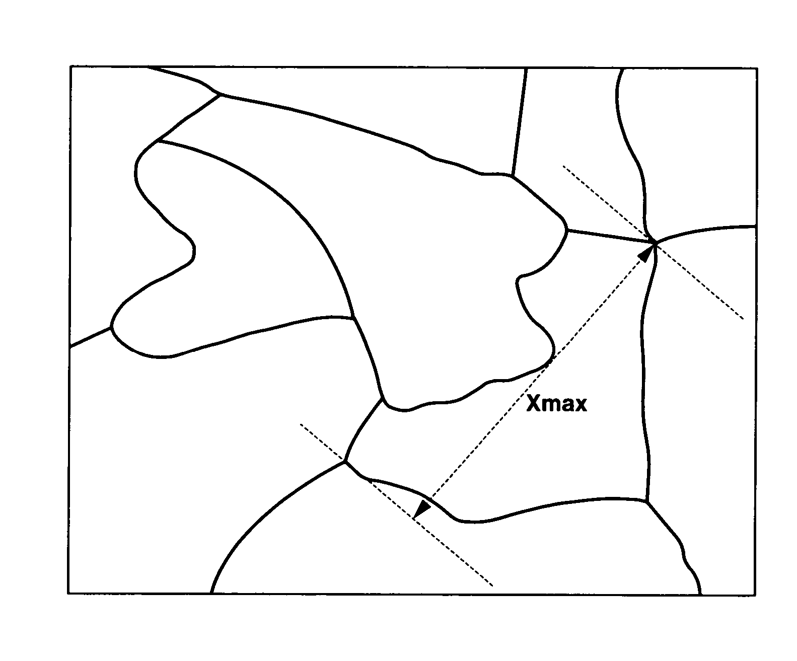
[0063]Metallic yttrium in particulate form containing not more than 100 ppm of each of metal elements other than rare earth, Na, K, Ca, Mg, Fe, Cr, Cu, Ni, Zn and Al, was melted by electron beam bombardment and solidified into an ingot of 50 mm×50 mm×200 mm. The ingot was analyzed for oxygen by an IR combustion method using EMGA-650 (Horiba Mfg. Co., Ltd.), detecting an oxygen content of 1.0% by weight. The ingot was sliced by wire cut EDM to form a plate of 5 mm×20 mm×20 mm or 5 mm×40 mm×100 mm. The machined surface was brass colored due to brass contamination. The plate was dipped in an aqueous solution of 0.25 mole / L citric acid for 10 minutes, while stirring. After the acid cleaning, the plate was washed with flowing deionized water, dipped in deionized water in a ultrasonic agitation tank for 5 minutes, and washed again with flowing deionized water.

[0064]The metallic yttrium plate as surface cleaned was analyzed in depth by glow discharge mass spectroscopy (glow discharge mass ...

example 2

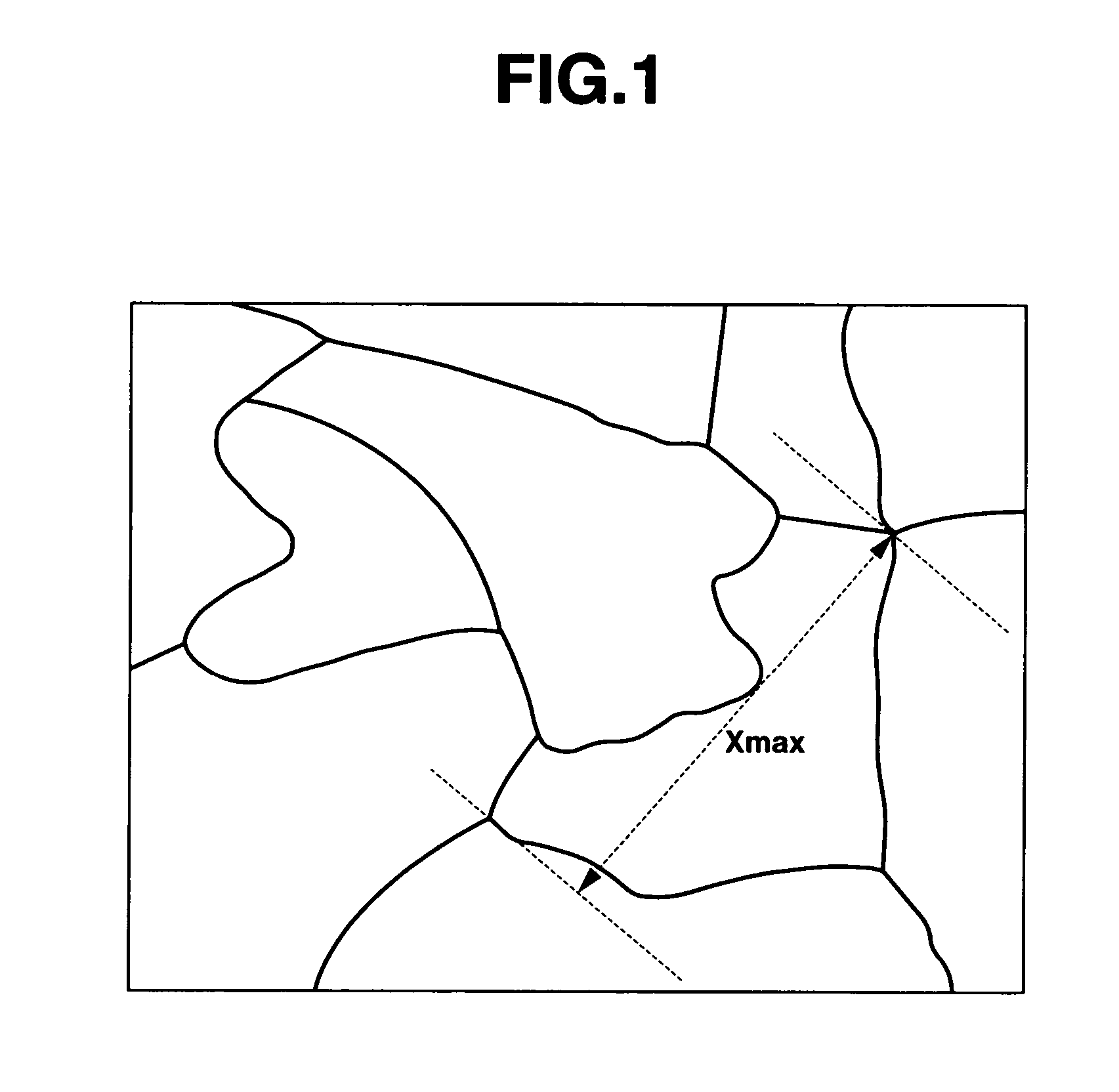
[0067]The procedure of Example 1 was repeated aside from using metallic dysprosium in particulate form containing not more than 100 ppm of each of metal elements other than rare earth, Na, K, Ca, Mg, Fe, Cr, Cu, Ni, Zn and Al. A metallic dysprosium plate was formed, surface cleaned with citric acid aqueous solution, and analyzed. The results of glow discharge mass spectroscopy are shown in Table 1. The results of plasma etching test are shown in Table 2. The grain size was 5.7 mm. The surface resistivity was 2.056×10⁻⁴ Ω / square when measured as in Example 1.

example 3

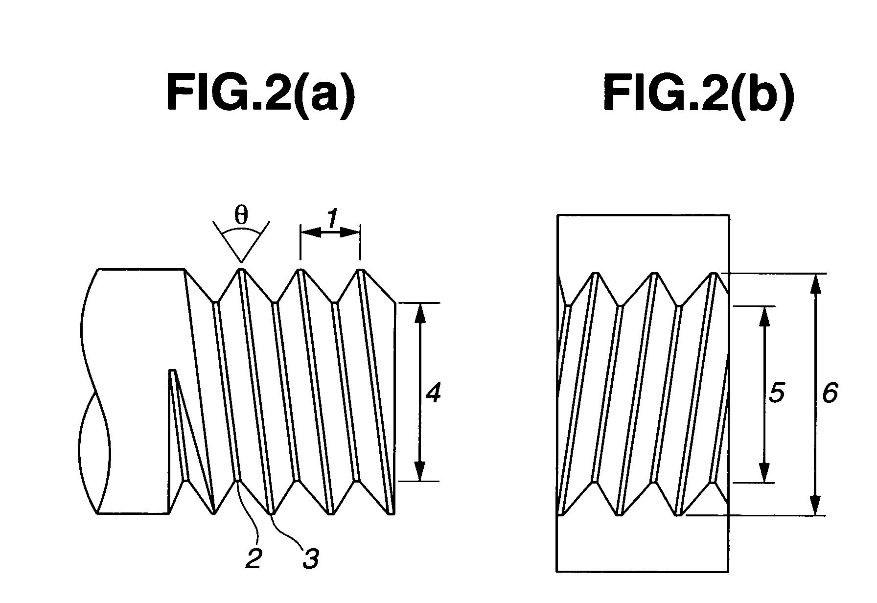
[0071]Metallic yttrium in particulate form was melted by electron beam bombardment and solidified into a rectangular ingot of 150 mm×100 mm×20 mm. The ingot was analyzed for oxygen by an IR combustion method, detecting an oxygen content of 1.1% by weight. The ingot was cut by a band saw into pieces of 150 mm×20 mm×20 mm, which were machined by a lathe / milling machine into hexagon head bolts and hexagon nuts of the ISO standard M6 size. For removing the grinding fluid, the bolts and nuts were immersed in ethanol where ultrasonic cleaning was performed. They were then dipped in an aqueous solution of 0.25 mole / L citric acid where ultrasonic cleaning was performed. They were washed with a large volume of deionized water for removing the citric acid. Bolts and nuts of yttrium were obtained in this way.


PUM

PropertyMeasurementUnit
grain sizeaaaaaaaaaa
depthaaaaaaaaaa
thicknessaaaaaaaaaa

Abstract

By using a rare earth metal having a minimal content of impurity metal element, machining it into a member and cleaning with an organic acid-base capping agent, there is obtained a rare earth metal member composed entirely of a rare earth metal and containing not more than 100 ppm of impurity metal element in a sub-surface zone, which member is characterized by a high surface purity, a large grain size, minimized grain boundaries, and improved halogen resistance or corrosion resistance.

Description

CROSS-REFERENCE TO RELATED APPLICATION[0001]This non-provisional application claims priority under 35 U.S.C. §119(a) on Patent Application Nos. 2005-189811 and 2005-189830 filed in Japan on Jun. 29, 2005 and Jun. 29, 2005, respectively, the entire contents of which are hereby incorporated by reference.TECHNICAL FIELD[0002]This invention relates to members of high purity rare earth metals, especially rare earth metal members having an extremely high surface purity, and rare earth metal members provided with helical grooves. More particularly, it relates to rare earth metal members composed entirely of rare earth metals which are resistant to corrosion with halogen-base corrosive gases or plasma thereof so that they are suited for use in semiconductor manufacturing equipment and flat panel display manufacturing equipment such as LC, organic EL and inorganic EL manufacturing equipment; and a method for preparing the same.BACKGROUND ART[0003]Semiconductor manufacturing equipment and fla...

Claims


Application Information

Patent Timeline
Patent Type & Authority Patents(United States)
IPC IPC(8): C22C28/00C23G1/02E01B9/10F16B33/00
CPCC22B59/00C22C28/00C23G1/10H01J37/32477H01J37/32431Y10S438/968H01J2237/022C23F4/00
Inventor TSUKATANI, TOSHIHIKONAKANO, HAJIMEMAEDA, TAKAO
Owner SHIN ETSU CHEM IND CO LTD
Learn More