Daylighting film

Inactive Publication Date: 2016-09-22
SHARP KK
View PDF14 Cites 17 Cited by
  • Summary
  • Abstract
  • Description
  • Claims
  • Application Information

AI Technical Summary

Benefits of technology

[0022]According to one aspect of the present invention, the daylighting film is provided which can realize high adhesion performance betwe

Problems solved by technology

In the case of pasting the daylighting film to the window glass, if structural elements (projections) with the daylighting function are

Method used


Image

  • Daylighting film
  • Daylighting film
  • Daylighting film

Examples


Example

First Embodiment

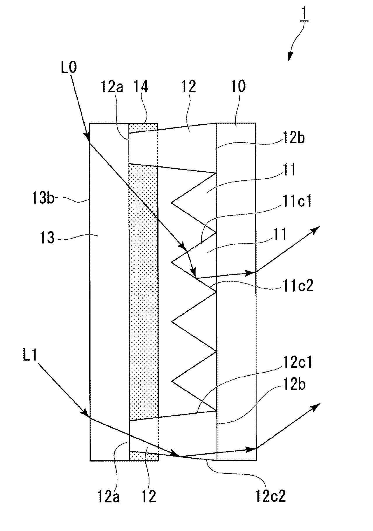
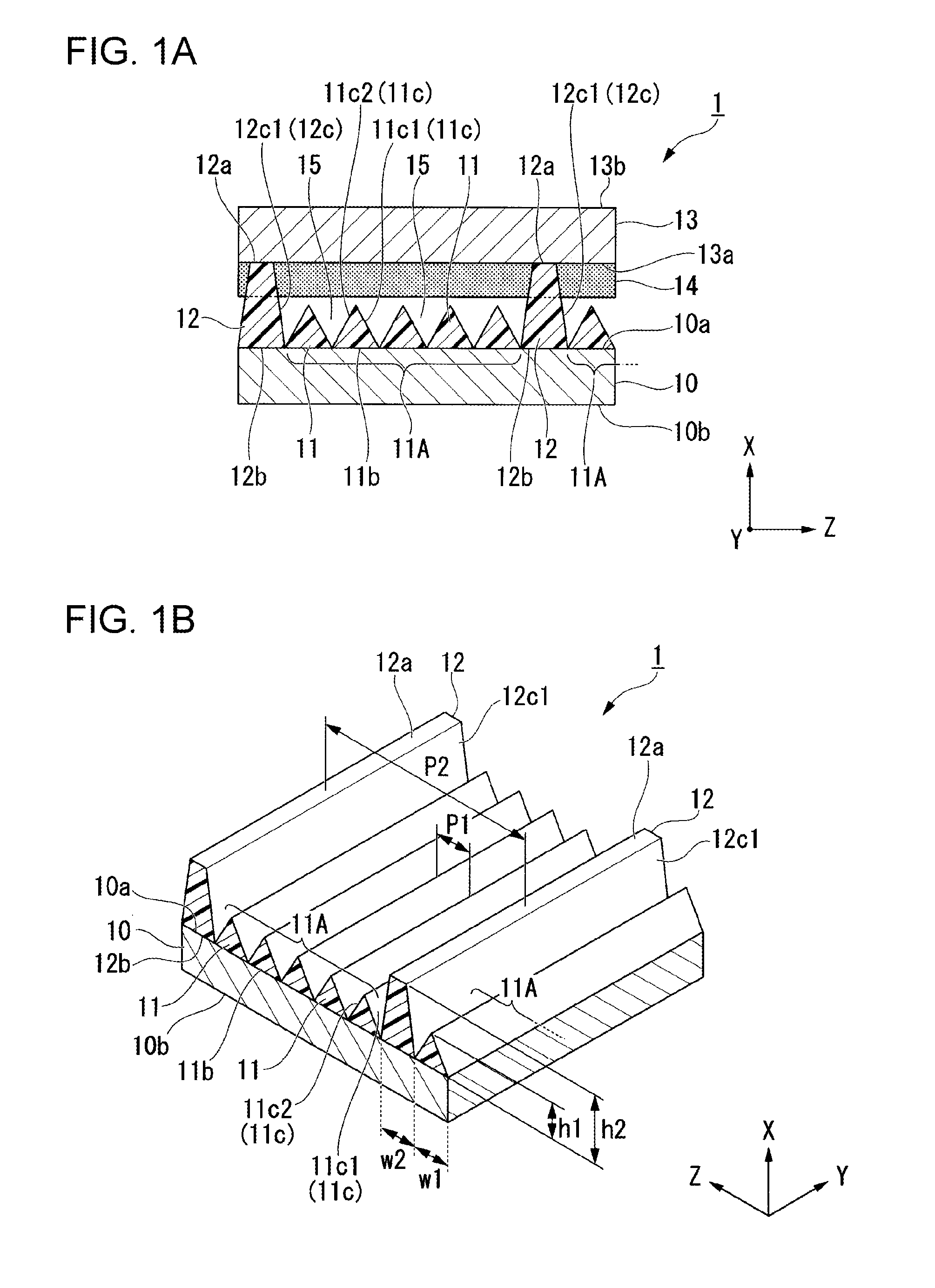
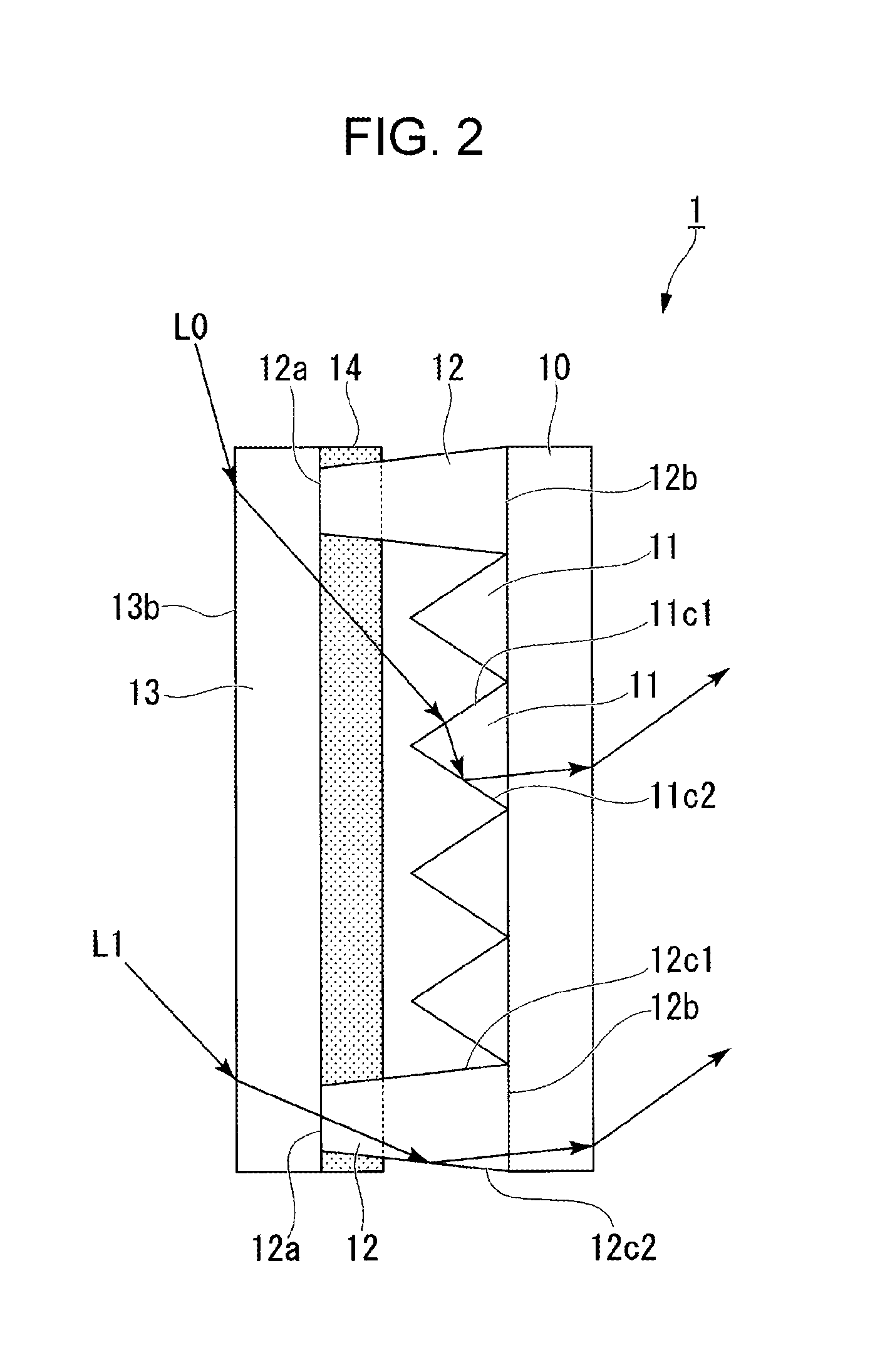
[0092]FIG. 1A is a perspective view schematically illustrating a constitution of a daylighting film 1 according to a first embodiment of the present invention, and FIG. 1B is a perspective view schematically illustrating a constitution of a base member 10. FIG. 2 is a sectional view schematically illustrating the constitution of the base member 10. In other words, FIG. 2 is an illustration referenced to explain a propagation direction of light passing through the daylighting film. It is to be noted that, while FIGS. 1A, 1B and 2 illustrate only six first projections 11 and only two second projections 12, the first projection 11 and the second projection 12 are each actually formed in a large number on the base member 10. This point is similarly applied to the other drawings.

[0093]As illustrated in FIGS. 1A and 1B, the daylighting film 1 includes a base member (first base member) 10 having optical transparency. On an inner surface (first surface) 10a of the base membe...

Example

[0121]FIG. 5 is a sectional view schematically illustrating a constitution of a daylighting film according to a second embodiment of the present invention.

[0122]It is to be noted that components in the second embodiment common to those in the first embodiment are denoted by the same reference signs, and detailed descriptions of those components are omitted.

[0123]A daylighting film 20 illustrated in FIG. 5 includes, as the projections used for the bonding, projections (second projections) 22 each having a triangular shape in a cross-section (XZ-section). The projections 22 are each formed in a height from the base member 10 higher than that of the first projection 11, and are bonded to the protective base member 13 in such a state that their tip portions are buried in the bonding layer 14. Since the tip portion of each projection 22 used for the bonding is pointed, the tip portion can be more easily buried into the bonding layer 14, and an amount of the bonding layer 14 displaced by ...

Example

Third Embodiment

[0129]FIG. 8 is a sectional view schematically illustrating a constitution of a daylighting film according to a third embodiment of the present invention.

[0130]It is to be noted that components in the third embodiment common to those in the first embodiment are denoted by the same reference signs, and detailed descriptions of those components are omitted.

[0131]As illustrated in FIG. 8, a daylighting film 30 according to this embodiment includes the first projections 11 and the second projections 12 both having optical transparency and formed on the inner surface 10a of the base member 10, the protective base member 13 arranged in an opposite relation to the inner surface 10a of the base member 10, the gap 15 defined between the first projections 11 adjacent to each other, the gap 15 defined between the first projection 11 and the second projection 12, a gap 15A defined between the second projections 12 adjacent to each other, and the bonding layer 14 filled into the ...


PUM


Abstract

A daylighting film (1) according to one aspect of the present invention includes a base member (10) having optical transparency, first projections (11) having optical transparency and formed on an inner surface (10a) of the base member (10), a second projection (12) formed on the inner surface (10a) and having a height from the inner surface (10a) higher than a height of the first projections (11), a protective base member (13) arranged in an opposite relation to the inner surface (10a) of the base member (10), a bonding layer (14) for bonding the second projection (12) and the protective base member (13), and gaps (15) defined between the first projections (11) and between the first projection (11) and the second projection (12), wherein the first projections (11) include reflective surfaces (11c2) at which light incoming from an outer surface (13b) side of the protective base member (13) or the base member (10) is totally reflected.

Description

TECHNICAL FIELD[0001]The present invention relates to a daylighting film.[0002]This application claims the priority on the basis of Japanese Patent Application No. 2013-235051 filed in Japan on Nov. 13, 2013, the entire contents of which are hereby incorporated by reference.BACKGROUND ART[0003]One example of known techniques for efficiently guiding light incident on a window glass into the indoor is disclosed in Patent Literature (PTL) 1. According to the technique disclosed in PTL 1, a daylighting film includes a plurality of unit prisms, which have the daylighting function and which are formed on one surface of an optically-transparent support, and the daylighting film is pasted to an outer surface (outdoor side surface) of the window glass with the unit prisms facing the outside. Light incident on the daylighting film from the unit prism side is refracted at surfaces of the unit prisms and enters the indoor after passing through the unit prisms, the support, and the window glass....

Claims


Application Information

Patent Timeline
IPC IPC(8): F21S11/00G02B17/00G02B7/182
CPCF21S11/007G02B17/006G02B7/182E06B3/66E06B5/00F21S11/00E06B3/67G02B5/045G02B5/00
Inventor SAKURAGI, KAZUYOSHIKAMADA, TSUYOSHIUEKI, SHUNNANGO, TOMOKOTSUJIMOTO, MASAHIROTSUDA, YUHSUKE
Owner SHARP KK
Why Eureka
Try Eureka