High installation performance blown optical fibre unit, manufacturing method and apparatus

a technology of optical fibre and manufacturing method, applied in the direction of optics, fibre mechanical structure, instruments, etc., can solve the problems of inconvenient access to optical fibers, poor installation performance of fibre optic cables, and inconvenient installation of optical fibers, so as to improve the air-blown installation performance

Active Publication Date: 2016-09-22
PRYSMIAN SPA
View PDF8 Cites 8 Cited by
  • Summary
  • Abstract
  • Description
  • Claims
  • Application Information

AI Technical Summary

Benefits of technology

[0014]The Applicant has faced the problem of providing a blown optical fiber unit for air-blown installation providing high installation performance while ensuring an easy access to the optical conductors inside the unit.
[0017]Differently from some other prior art arrangements, there is no gap between the resin material and the outer layer. This improves the air-blown installation performance.

Problems solved by technology

However, such arrangements have the shortcoming that, due to the presence of particulate material, the access to the optical fibers is not deemed to be easy.
The Applicant has realized that the fibre optic cable according to WO 2004 / 015475 A2 does not provide a good installation performance.
According to the Applicant, the installation performance of the fibre optic cable according to WO 2004 / 015475 A2 are negatively affected, inter alia, by the gap between the outer layer and the inner layer.
This material provides a high friction which is undesirable for an optical fibre cable designed for air-blown installation.
The Applicant has realized that the cable of U.S. Pat. No. 6,334,015 is rather flexible and this characteristic results in rather low blowing performance.
The outer surface of the cable may be covered with oil or grease and this is inconvenient.

Method used


Image

  • High installation performance blown optical fibre unit, manufacturing method and apparatus
  • High installation performance blown optical fibre unit, manufacturing method and apparatus
  • High installation performance blown optical fibre unit, manufacturing method and apparatus

Examples


Embodiment Construction

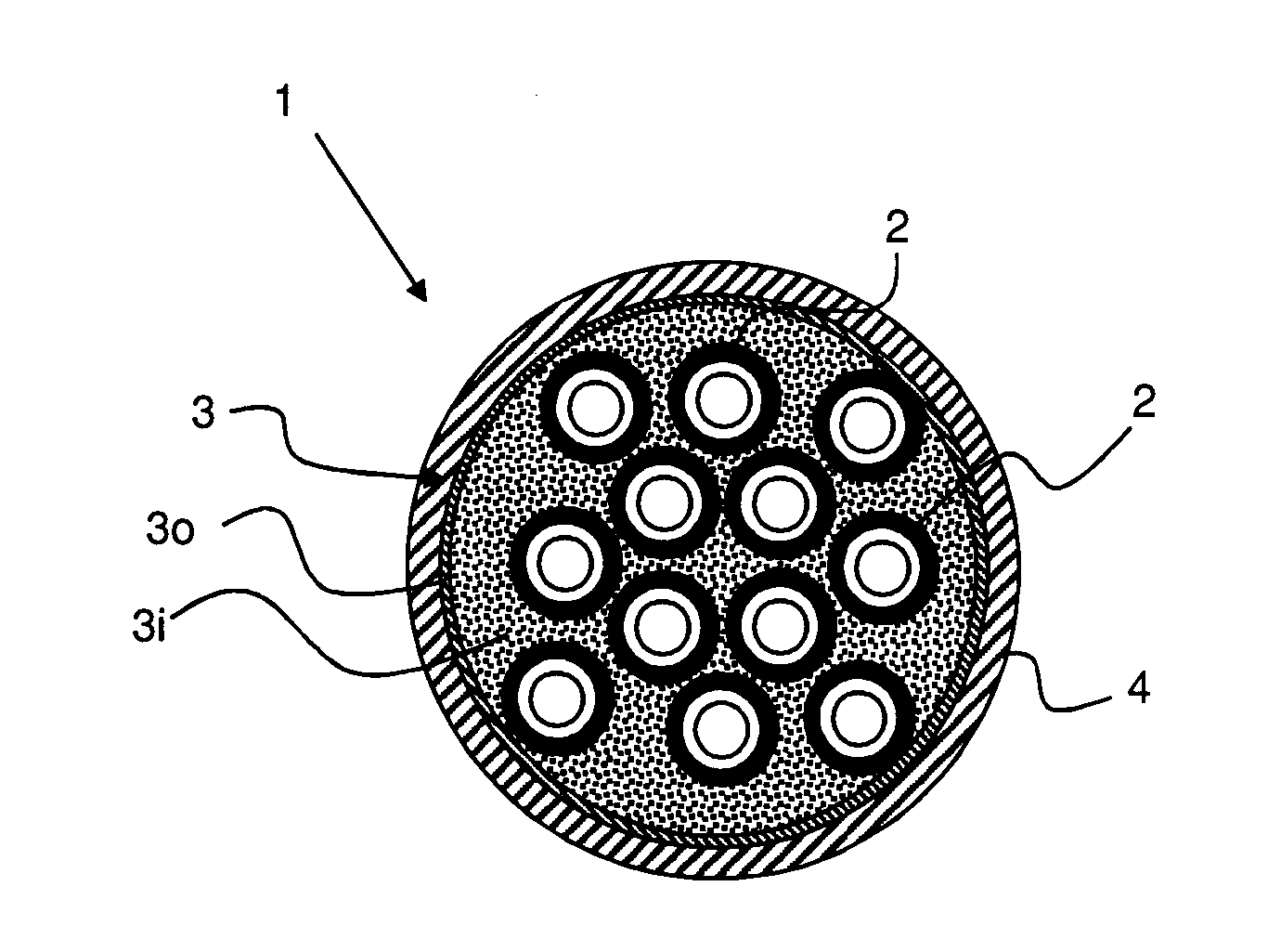
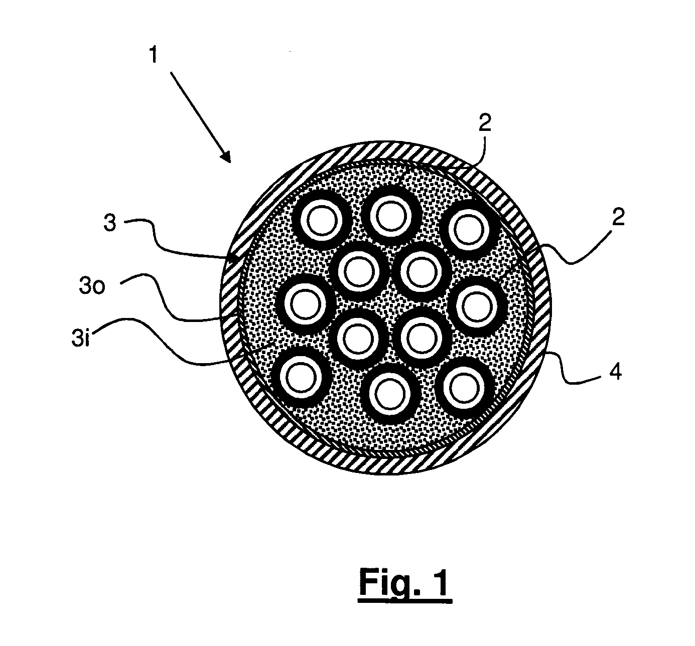
[0045]FIG. 1 represents a schematic cross-section of a blown optical fibre unit 1 according to a first example of the present invention.

[0046]The optical fiber unit 1 comprises a plurality of optical conductors 2. In the example of FIG. 1 twelve optical conductors 2 are provided. However, in other examples (not shown) the number of optical conductors 2 could be higher or lower than twelve.

[0047]Preferably, each of the optical conductor 2 is substantially the same as the other optical conductors. However, within the scope of protection of the present invention are also examples wherein the optical conductors differ in terms of, for instance, outer diameter, material of the outer layer and properties of the optical core.

[0048]Each of the optical conductors 2 preferably comprises an optical coated fibre. The term “optical fibre” is meant to indicate an optical glass core surrounded by a glass cladding and a coating system comprising one or two layers of cured resins, for example acryla...


PUM


Abstract

An optical fiber unit for air-blown installations includes a number of optical conductors, a first layer of resin material, a second layer of resin material radially outer to the first layer of resin material and a sheath of a thermoplastic material, wherein the second layer of resin material has a secant modulus higher than a secant modulus of the first layer of resin material and wherein the sheath of thermoplastic material is over and in close contact with the second layer of resin material.

Description

BACKGROUND[0001]The present invention relates to optical fibre units for air-blown installations. More in particular, the present invention relates to a blown optical fibre unit providing high installation performance. The present invention also relates to an apparatus and a method of manufacturing such a blown optical fibre unit.PRIOR ART[0002]Fiber optic cables have been commonly deployed by installing them in ducts by blowing or pulling, burying them in the ground, or suspending them between above-ground poles.[0003]Optical microcabling technology has been introduced for the deployment of fiber optic cables to increase use of the conduit space and to enhance profitability of the current (and / or future) telecommunications infrastructure. This technology involves the use of standard inner ducts in which microducts are jetted, followed by the jetting of microduct cables or microcables into the microducts when required. Although originally intended for business access networks (FTTB)...

Claims


Application Information

Patent Timeline
Patent Type & Authority Applications(United States)
IPC IPC(8): G02B6/44
CPCG02B6/4438G02B6/4486G02B6/4433G02B6/52
Inventor SUTEHALL, RALPHDAVIES, MARTINPADDICK, NATHANROBERTS, PAULLANG, IAN DEWIMASON, MARK RICHARD
Owner PRYSMIAN SPA
Why Eureka
Try Eureka